background image

Operation

20 

Dimple Grinder User’s Guide

microscope. The exact time needed to polish the specimen will vary depending 
on hardness.

4.8 Polishing to Final Thickness < 20 µm

Producing a dimpled area of < 20 µm thickness requires extended polishing 
with the felt wheel. The specimen has to be first coarsely polished and finished 
with a fine polish. The micrometer is not used because the softness of the felt 
makes it impossible to obtain an accurate reading. 

Dimpling progress can be easily monitored for specimens on glass mounts 
when viewed in transmitted light on the microscope. In the case of semiconduc-
tors, the color of the specimen as seen with transmitted light is closely related to 
thickness. For silicon, red indicates a thickness of about 10 µm while yellow 
indicates a thickness around 5 µm for (100) orientation.

4.8.1 Coarse Polishing

When a specimen thickness of 15-20 µm has been reached by grinding, the 
specimen is thoroughly cleaned and the grinding wheel replaced with a felt pol-
ishing wheel. The object of the coarse polishing stage is to remove the scratches 
and other mechanical damage resulting from grinding and to produce a specular 
surface.

To coarse polish

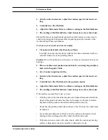
Set the Counterweight to 20 g and the wheel speed to mid range.

Use a 2–4 µm diamond compound on the specimen and the wheel. 

Silicon normally requires coarse polishing for about 5 minutes. This time 
should be split into short periods interspersed by cleaning of the specimen and 
wheel with a cotton swab and distilled water followed by acetone or other sol-
vents.

4.8.2  Fine Polishing

The object of the fine polishing stage is to very gently reduce the specimen 
thickness to less than 2 µm. The specimen must be completely cleaned of all 
traces of the previous polishing compound. Lack of care in accomplishing this 
will make it impossible to thin the specimen as required.

To fine polish

Mount a new, clean felt polishing wheel.

Set the Counterweight to 20 g and the wheel speed to mid range.

Summary of Contents for 656

Page 1: ...Dimple Grinder Model 656 User s Guide Gatan Inc 5933 Coronado Lane Pleasanton CA 94588 Tel 925 463 0200 FAX 925 463 0204 November 1998 Revision 2...

Page 2: ...Part Number 656 82002...

Page 3: ...The Dimple Grinder User s Guide includes the following sections Section 1 Overview provides an overview of the system Section 2 Installation provides instruction for installation of the unit Section 3...

Page 4: ...her reserves the right to revise this manual and to make changes to its contents at any time without obligation to notify any person or entity of such revisions or changes Copyright and Trademarks Gat...

Page 5: ...earest you or contact by electronic mail Gatan Inc USA West Coast Tel 925 463 0200 Fax 925 463 0204 Gatan Inc USA East Coast Tel 724 776 5260 Fax 724 776 3360 Gatan GmbH Germany Tel 089 352 374 Fax 08...

Page 6: ...iv Dimple Grinder User s Guide...

Page 7: ...ng Devices 2 3 3 Counterweight 4 3 4 Specimen Rotation Axis 5 3 5 Wheel Types 5 3 6 Raise Lower Cam 8 3 7 Stereo Microscope 8 3 8 Specimen Mounts 9 4 0 Operation 10 4 1 Adjusting Zero of Dial Indicato...

Page 8: ...5 0 Performance Check 22 5 1 Arm Pivot Friction 23 5 2 Zero Counterweight Scale 23 5 3 Eccentricity Run Out 24 5 4 Vertical Movement of the Specimen Turntable 26 5 5 Grinding Wheel Alignment 26 5 6 Mi...

Page 9: ...view 3 Figure 2 Measuring devices 4 Figure 3 Grinding wheel rotation axis 5 Figure 4 Wheel position alignment 6 Figure 5 Wheel types 7 Figure 6 Stereo microscope 9 Figure 7 Specimen mounts 10 Figure 8...

Page 10: ...viii Dimple Grinder User s Guide...

Page 11: ...removed with additional final thinning by electro polishing ion beam thin ning etc A final specimen thickness of 5 m can routinely be produced by a careful operator The Dimple Grinder is gentle enoug...

Page 12: ...top of this base sits a pivoted Platform containing the Grinding Wheel assembly the analog Dial Indicator and the Counterweight The Platform when in the vertical position is held in place by a magneti...

Page 13: ...0 11 1 Zero stop 2 Raise lower cam control 3 Analog dial indicator 4 Autoterminator socket 5 Pivot platform 6 Load scale 7 Counterweight 8 Microscope socket 9 Wheel motor socket 10 Main power On Off s...

Page 14: ...unted to the Platform The raising of the stylus results in a corre sponding raising of the grinding wheel A desired dimple depth shown in the digital readout can be set using the Micrometer see Sectio...

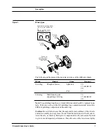
Page 15: ...of the specimen rotation axis and hence con tacts the specimen at the correct point Figure 3 Grinding wheel rotation axis The correct configuration is determined by the appropriate wheel diameter and...

Page 16: ...ted to tougher specimens particularly metals Wheels come in different sizes The small wheel preserves a wide thick rim around the thin area for fragile specimens and produces steep profiles for analy...

Page 17: ...e assembly are kept clean Do not flood the male taper with solvents to clean the axle as this may flush grit or compounds into the axle assembly lead ing to wear and impaired performance Clean the axl...

Page 18: ...he stereo microscope see Figure 6 projects a true image and is designed to accurately fit the microscope mount around the Magnetic Turntable The cross hair within the eyepiece is aligned to the center...

Page 19: ...ard 15 mm diameter wheel is cylin drical in shape and made of stainless steel Opaque specimens are normally mounted on the stainless steel mount For transparent specimens or for materi als that become...

Page 20: ...men mounts should be periodically checked for smoothness and flatness This may be done either with the stereo microscope or a free standing dial indicator 4 0 Operation There are two methods by which...

Page 21: ...den significantly and these are best dimpled at a slow speed with reduced load Grinding by Dimple Depth This method is used when very thin 20 m specimens are being dimpled The Micrometer is first zero...

Page 22: ...he Cam stop is in the rear position 4 Lower the micrometer end face by rotating the Micrometer Drive clockwise until it bottoms against the base 5 Use the Raise Lower Cam and carefully lower the Platf...

Page 23: ...ently strong supporting rim that allows for subsequent ion milling at low angles Dimpling Techniques For normal dimpling disc grinding can be completed using 5 m paper but for thinning of specimens to...

Page 24: ...ount Note Until you have perfected the technique for mounting specimens check the thickness of the wax layer It should be less than 3 m 4 4 Specimen Positioning The Magnetic Turntable allows the dimpl...

Page 25: ...e off 4 Lower the micrometer end face by rotating the Micrometer Drive clockwise 5 Place the mount plus specimen and centering ring on the Magnetic Table Carefully lower the grinding wheel onto the sp...

Page 26: ...and the specimen surface and grinding wheel must not be permitted to dry out Also it is recommended the wheel and specimen be occasionally cleaned and fresh diamond compound applied 4 6 Set Grinding b...

Page 27: ...g on the digital display will be negative 9 Use the Cam and carefully lower the grinding wheel onto the specimen The Dial Indicator now displays the thickness of material to be removed This value plus...

Page 28: ...ness 0 000 Specimen mount with specimen 0 015 0 000 0 Zero stop Analog dial indicator Grinding wheel Spring loaded stylus Digital display Specimen mount without specimen Micrometer head raised Digital...

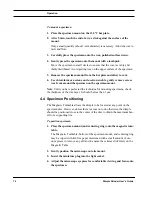
Page 29: ...und Use a cotton swab and distilled water followed by flushing with acetone 3 Carefully mount the polishing wheel onto the axle 4 Place the specimen mount back onto the Turntable and center using the...

Page 30: ...een reached by grinding the specimen is thoroughly cleaned and the grinding wheel replaced with a felt pol ishing wheel The object of the coarse polishing stage is to remove the scratches and other me...

Page 31: ...that together they come to less than the original specimen thick ness To do double sided dimpling 1 After dimpling the first side the specimen is removed from the mount Note Thoroughly clean the speci...

Page 32: ...f surface segregation platings coat ings etc Dimple depth into the specimen is represented by the following equa tion Depth x 2r x 2R where R wheel diameter r dimple radius x distance from the edge of...

Page 33: ...latform to gen tly fall towards the horizontal or rise to about 60 Note This is not the zeroing of the Counterweight scale 5 2 Zero Counterweight Scale The load scale is friction coupled to the Counte...

Page 34: ...the Dial Indicator needle within one divi sion of zero by adjusting the Counterweight no more than 2g from the load scale zero 5 3 Eccentricity Run Out Excessive vertical movement of the Platform mak...

Page 35: ...steel specimen mount into the centering ring and place both on the Magnetic Table 3 Set a Counterweight load of 20 g 4 Switch on the wheel motor adjust the rotation speed to the lowest set ting 5 Car...

Page 36: ...not flood the axle with solvent as this may wash grit into the axle bearings 2 Place a stainless steel specimen mount into the centering ring and place both on the Magnetic Table Use the cross hair of...

Page 37: ...int should be a small circular spot centered within the cross hair of the stereo microscope Note Should the point of contact appear as a ring instead of a spot it indicates the pivoted Platform is out...

Page 38: ...5 Raise the pivoted Platform 6 Push from below the stylus of the Dial Indicator against the zero stop screw overriding the clutch Push with the hex wrench 7 Screw in the zero stop screw until it is f...

Page 39: ...flathead socket screw on the base Raise the Platform to its vertical position to expose the flathead socket screw Use the 3 32 hex wrench to remove this screw 3 Expose the PC board Pull off the SPEED...

Page 40: ...656 07062 Spherical grinding wheel stainless steel 10 mm wheel x4 656 07063 Spherical grinding wheel phosphor bronze 15 mm wheel x4 656 07064 Spherical grinding wheel stainless steel 15 mm wheel x4 6...

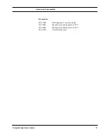
Page 41: ...nsumables Dimple Grinder User s Guide 31 Accessories 601 07000 TEM Specimen Cross Section Kit 623 40001 Specimen mounting hot plate 120 V 623 40002 Specimen mounting hot plate 240 V 656 0150T Axle cal...

Page 42: ...Spares and Consumables 32 Dimple Grinder User s Guide...

Page 43: ...tion 23 eccentricity run out 24 grinding wheel alignment 26 turntable vertical movement 26 zero counterweight scale 23 zero stop adjust 28 R Raise Lower cam 8 S Specimen mounting 13 polishing 19 coars...

Page 44: ...I 2 Dimple Grinder User s Guide...

Page 45: ...972 3 532 5696 General Engineers Ltd P O Box 557 Herzliya 46105 Israel Italy 2M Strumenti Srl Via Pontano 9 00141 Roma Italy 011 39 68689 5319 011 39 68689 5241 Japan Enomoto Analytical Vacuum Instr C...

Page 46: ...192 68 Sollentuna Sweden 011 46 8 626 8365 011 46 8 626 8355 Switzerland Gloor Instruments AG Herr Fritz Gloor Brauereistrasse 10 CH 8610 Uster Switzerland 011 411 940 9955 011 411 940 9914 Republic o...

Page 47: ...mber may be obtained through Gatan Service or directly from Gata s Warrendale facility at 412 776 5260 If the item is not under warranty to obtain an RGA the customer must provide a Purchase Order PO...

Page 48: ......
Page 49: ...O THE FOLLOWING EUROPEAN DIRECTIVES Low Voltage Directive 73 23 EEC EMC Directive 81 336 EEC As Modified by Directive 93 68 EEC Supplementary Information Safety EN 61010 1 1991 A2 1995 EMC EN 55022 Cl...

Reviews: