140
PIPS II Owners Manual and Users Guide
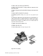
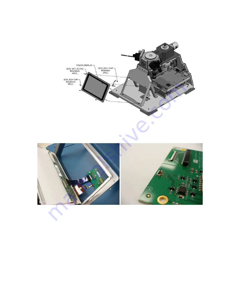
Figure 5-24 Touch display assembly.
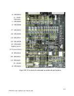
Figure 5-25 Connections for touch display.
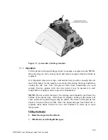
Left image shows cable connections made prior to attaching the touch display.
Right image shows the clamp for the touchscreen cable in the open position.
After the touchscreen cable is inserted into this connector, press down on this
clamp. Note that this is a delicate connection.


