143
PIPS II Owners Manual and Users Guide
11.
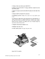
Remove the 4 screws that secure the I/O PCA.
12.
Remove the nuts from the CC Gauge and Dewar connectors on the
back of the system.
13.
Remove the jack screws from the RS-232 connector on the back of the
system.
14.
Remove the PCAs from the PCA enclosure.
15.
Install the new PCAs.
Replace the 4 screws, the 2 nuts, and the 2 jack
screws.
16.
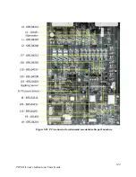
Connect the cables to the same sockets they were removed from.
The
captive connectors have an orientation defined by a chamfer on two corners.
The image below shows the location of the sockets, and each cable should be
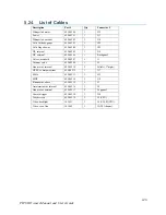
labeled with the connector. In addition, the List of Cables shows the
associated connector for each cable.
17.
Replace the electronics enclosure cover.
18.
Replace the system cover.
19.
Power on the system.
First replace the power cable.
Figure 5-28 PCA assembly.


