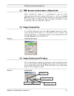
background image


Quadrant Correction Reference 


UltraScan Use

r

’s Guide Reference Series Rev 1.0 

2-6 

2.4  Quadrant Correction Reference 


The above 

Set Bias Levels

 routine removes gross contrast variation from 

quadrant to quadrant. The remaining variation can be removed by  the Prepare 
Quadrant Correction Reference routine. 

Before running the 

Prepare Quadrant Correction  Reference

 routine, make 

sure the CCD has reached its stable temperature (reading from the front panel 
of the First Light controller).  

Remove the sample from the field of view and spread the illumination evenly 
across the CCD sensor (similar to “prepare gain reference” image). 

Under 

Camera

 menu (Figure 2-3a), run  the 

Prepare Quadrant Correction 

Reference

 routine.  Set the target intensity so the center of the intensity 

indicator is in the green region (Figure  2-4).  Follow the instructions on the 
screen. This is a time consuming procedure as images with various exposures 
are recorded to cover full intensity range. It typically takes about  50 and  75 
minutes for US1000 (2k x 2k) and US4000 (4k x 4k) respectively.  Once the 
procedure completes, a reference image is stored in DigitalMicrograph 
“Reference Images” folder for later use. 

Typically it is not required to run this routine frequently. 

It is important to run 

Gain normalization

 routine (next section) after 

Prepare 

Quadrant Correction  Reference

 in order to activate the linearization 

correction routine, so that it is applied to all the future acquired images.  

2.5  Gain Normalization 


It is important to prepare a new gain reference image after the CCD has reached 
the equilibrium temperature (normally this takes about 1-2 hours).  The gain 
reference image should be checked regularly.   

To prepare gain reference image, remove specimen from the field of view, 
evenly spread the illumination across the CCD sensor. 

Under the 

Camera

 menu (Figure 2-3), choose 

Prepare Gain Reference

.  Set 

the target intensity to the value of 10,000-20,000 (for US4000, it may be 
necessary to set the target intensity close to 10,000  counts since the CCD may 
saturate around 20,000 counts. See  the  “Most  Often  Asked  Questions” in 
section 5 for details).  Normally it is sufficient to set the frames to average to 4.  
Then simply follow the instructions on the screen.  

It is recommended to perform this operation when  


The camera temperature is stable (check the temperature display on the 
controller front panel),  


Every time the camera is switched on,  
Summary of Contents for UltraScan 895

Page 1: ...UltraScan User s Guide Reference Series Gatan Inc 5933 Coronado Lane Pleasanton CA 94588 Tel 925 463 0200 FAX 925 463 0204 January 2003 895 MANUAL Revision 1 0...

Page 2: ...software and prepare for the acquisition of an image Gain Normalization and Magnification Calibration Chapter 3 Image Acquisition shows the user the most often used floating windows in DigitalMicrogra...

Page 3: ...ms any implied warranties of merchantability or fitness for a particular purpose Gatan Inc further reserves the right to revise this manual and to make changes to its contents at any time without obli...

Page 4: ...contact by electronic mail Gatan USA West Coast Tel 925 463 0200 Fax 925 463 0204 Gatan USA East Coast Tel 724 776 5260 Fax 724 776 3360 Gatan Germany Tel 089 352 374 Fax 089 359 1642 Gatan UK Tel 018...

Page 5: ...CAMERA CONFIGURATION 2 3 2 3 SET BIAS LEVELS 2 4 2 4 QUADRANT CORRECTION REFERENCE 2 6 2 5 GAIN NORMALIZATION 2 6 2 6 MAGNIFICATION CALIBRATION 2 7 2 6 1 Low magnification 2 8 2 6 2 High magnification...

Page 6: ...N ASKED QUESTIONS 5 4 APPENDIX 1 I HARDWARE DESCRIPTION I A1 SYSTEM REQUIREMENTS I A2 DESCRIPTION II A2 1 FRONT PANEL CONTROLS IV A2 2 CONTROLLER S BACK PANEL VI A3 INSTALLATION IX A3 1 Pressure lines...

Page 7: ...5 CALIBRATION WINDOW 2 13 FIGURE 3 1 IMAGE WINDOW 3 2 FIGURE 3 2 FOCUS LOUPE 3 3 FIGURE 3 3 IMAGE INFO 3 3 FIGURE 3 4 CAMERA ACQUIRE WINDOW 3 4 FIGURE 3 5 SAVING WINDOW 3 4 FIGURE 3 6 SAVING SET UPWIN...

Page 8: ...ted High Contrast Resolution HCR optical technology HCR technology results in images with higher resolution and higher contrast than images acquired with traditional optics and takes digital imaging r...

Page 9: ...sure the water and the three color coded pressure lines are correctly connected to the camera and proper water pressure is maintained Switch on the CCD camera controller Fig 2 1 the LED will turn gree...

Page 10: ...lace When DigitalMicrograph is launched you will see the commonly used tools left side the Image Acquisition and Saving tools right side and the Result window as shown in Figure 2 1 These tools are co...

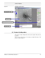
Page 11: ...2 2 Camera Configuration If the camera is already configured by a Gatan service engineer this section can be ignored Before starting acquiring images it is necessary to configure the camera This proc...

Page 12: ...he following r0 8 r4088 4095 c0 8 c4088 4095 r and c indicates row and c olumns respectively corrects for the 8 pixels wide edge which does not contain active CCD pixels in the case of the UltraScan 4...

Page 13: ...Controller This will remove the majority of the image contrast from quadrant to quadrant in an evenly illuminated flat field image and maximize the dynamic range The Set Bias Levels should be run befo...

Page 14: ...is stored in DigitalMicrograph Reference Images folder for later use Typically it is not required to run this routine frequently It is important to run Gain normalization routine next section after Pr...

Page 15: ...samples At Low magnifications Use cross grating sample or any sample having known spacing At High magnifications Use graphite or any crystalline samples having known lattice spacing Use the FFT method...

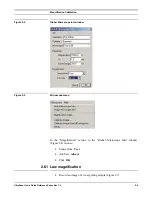
Page 16: ...2 8 Figure 2 5 Global Microscope Info window Figure 2 6 Microscope menu In the Magnification section in the Global Microscope Info window Figure 2 4 choose Source from User Ask User Always Click OK 2...

Page 17: ...he on screen instructions Figure 2 8 Figure 2 8 Instructions window A red line will appear on the image Position it on a feature of known size Press OK on the Calibrate image window Enter the correct...

Page 18: ...igure 2 9 to complete the magnification calibration Figure 2 10 Choose YES to complete the calibration The calibration can be checked on the calibration table containing pairs of value the nominal mic...

Page 19: ...n represents the nominal TEM magnification and the second column is the actual magnification at the CCD 2 6 2 High magnification Record a lattice image of the crystalline sample Figure 2 12 Figure 2 1...

Page 20: ...ollow the on screen instructions Figure 2 14 A red line will appear on the diffractogram Position the endpoints of the red line on two symmetrical diffraction peaks Figure 2 13 Press OK to specify the...

Page 21: ...Magnification Calibration UltraScan User s Guide Reference Series Rev 1 0 2 13 Figure 2 15 Calibration window...

Page 22: ...cus mode displays a continuous image at higher resolution than the Search image Fine adjustment of focus setting can be done with this operation mode In addition there is another way to adjust the ima...

Page 23: ...to respectively double or halves the exposure time To view a continuous image of the sample Select the Camera insertedbox or make sure it is selected Setup Search mode Press Start Viewto start the im...

Page 24: ...or Pressing the Spacebar 3 2 Image Notes The user can type in notes in the Image Info window shown in Figure 3 3 Saving an image will automatically save the image notes with the image file The Up down...

Page 25: ...cord the final image click on the Start Acquire button in the Camera Acquire palette shown in Figure 3 4 This mode is preset to acquire a full resolution CCD image As explained previously it is recomm...

Page 26: ...6 click on the Browse button Select or create a directory for saving images 3 5 2 Construct Image File Name In the File Name Options field specify the way you want the image file name to be constructe...

Page 27: ...Rev 1 0 3 6 Figure 3 7 Saving Data Bar Custom item allows user to add text information to every report page This feature is useful to add the name of your institution or the name of your TEM lab Click...

Page 28: ...ered in the window of the Single line item Click OK The style of the Custom item can be easily changed in the Report page next section 3 5 4 Report The report button the one with a page and a magnifie...

Page 29: ...style to make it more visible First position it on the Report page and then choose the font and size of your liking Click 3 5 5 Printing dimensions Digital images can not be magnified indefinitely sin...

Page 30: ...Image Saving and Printing UltraScan User s Guide Reference Series Rev 1 0 3 9 Figure 3 10 Control palette...

Page 31: ...it is recommended waiting 2 hours or more for the system to stabilize Flip the shutter switch to AUTO Turn the computer on if it is not on yet and double click in the DigitalMicrograph icon to launch...

Page 32: ...e 3 1 to check the final focus Make sure Auto Surveyis checked Click on Start Acquire button in the Image Acquire palette Figure 3 4 disable Auto Exposure Click on Report View button on the Saving win...

Page 33: ...h is illuminated when an over temperature condition is detected The first light controller monitors the temperature of the Peltier heat sink If the temperature exceeds 50 C an automatic protection wil...

Page 34: ...d in the viewing chamber and the CCD gate valve opens Removing large amounts of condensation will require the electronics to be switched off for about 30 minutes after the vacuum in the viewing chambe...

Page 35: ...inated Check the scintillator for oil contamination by acquiring an image at low kV about 60 kV to put in evidence surface s contaminations If you have a clean vacuum in the camera chamber area you ma...

Page 36: ...er resolution 1x binning readout mode does not make full use of the full range of the output amplifier because of the smaller pixel size The US4000 saturates at roughly 1 3 of the full digitization ra...

Page 37: ...are noisy what can I do Try increasing the exposure or current density of the beam 7 My images are slowly deteriorating what should I do Determine if the CCD is warming up Check the temperature displa...

Page 38: ...ntrolled by the CCD camera software In order to protect the CCD the software default setting shutter normally closed closes the TEM shutter if the CCD is not set to acquire any images In this case one...

Page 39: ...series CCD cameras the following hardware and software systems are required Windows 2000 Professional or Windows XP Professional Minimum 512 MB RAM 1GB RAM preferred 40GB 1GHz Hard drive or better Pen...

Page 40: ...image detection by the CCD pixel and also by cooling and low noise readout Resolution is achieved by minimizing light scatter in the scintillator and light leakage amongst fibers in the fiber optic pl...

Page 41: ...A2 Description UltraScan User s Guide Reference Series Rev 1 0 III Figure A 1 UltraScan TM Reference Series camera mounted on a TEM column Figure A 2 Controller s front panel Water line Air lines...

Page 42: ...panel shutter control Shutter Control Figure A3 LEDs 1 and 2 indicate the state of shutters 1 and 2 respectively An illuminated LED corresponds to a shutter Open state AUTO OPEN Switch Figure A3 When...

Page 43: ...ncy of the UltraScan camera Cool Off Warm Figure A4 Controls the camera s thermo electric cooler In the Cool mode the camera will maintain a temperature of 25 degrees Celsius The warm setting is used...

Page 44: ...Figure A5 Fiber 1 output transmits data from the Fiber Optic Interface card mounted in the PCI bus of the computer Fiber 2 input receives data from the controller to the Fiber Optic Interface card Out...

Page 45: ...onnections Figure A6 The microscope air line at 60 PSI is connected to the AIR IN connection located on the rear panel The camera insertion air line is connected to the AIR IN port If an inserted came...

Page 46: ...A2 Description UltraScan User s Guide Reference Series Rev 1 0 VIII Figure A 7 Controller s back panel...

Page 47: ...the computer anywhere that is convenient UltraScan System 1 Computer 2 TEM interface cable optional 3 Controller 4 Camera interface cable 5 Shutter interface cable 6 Camera interface cable 7 UltraScan...

Page 48: ...Fully retracted with both the scintillator and the CCD sealed inside a separate vacuum enclosure The air kit supplied with the camera consists of three sets of tubes two per set numbered 1 through 6...

Page 49: ...essed air line Cut the open line to the diffusion pump gate valve of the microscope s pneumatic system in two places The cuts must be made as cleanly as possible They can be made anywhere along the Op...

Page 50: ...the film chamber Follow the instructions given by the microscope manufacturer Inspect the o ring seal to the microscope for dust and fibers The seal must be clean in order to maintain the vacuum If n...

Page 51: ...e T to the two ends of the hose Cut the water chiller hose that runs from the microscope to the water chiller The cut must be made after any pressure regulation or flow restriction in the microscope p...

Page 52: ...a head Connect one end of line 4 to the water outlet on the camera head and the other end to line 5 to complete the loop The quick disconnect fittings automatically seal the lines off when not connect...

Page 53: ...e electrical connections in the system Figure A 11 Electrical diagram Connect the controller to the multiple outlet strip The computer should not be plugged into the outlet strip Run the camera cable...

Page 54: ...ler Figure A7 Connect one end of the Shutter Interface cable to the Shutter Control output on the controller Connect the other end to the Shutter Interface provided by Gatan or microscope vendor A3 6...

Page 55: ...UltraScan User s Guide Reference Series Rev 1 0 XVII Appendix 2 CE certification...

Page 56: ...UltraScan 1000 Model Number 895 894 CONFORMS TO THE FOLLOWING EUROPEAN DIRECTIVES Low voltage Directive 73 23 EEC EMC Directive 89 336 EEC As modified by Directive 93 68 EEC Supplementary Information...

Page 57: ...n patterns 5 2 5 3 digital camera 1 1 2 1 DigitalMicrograph i ii 1 1 2 1 2 2 2 3 2 7 3 8 4 1 dynamic range 1 1 5 4 E exposure time 3 1 5 3 5 5 F FFT 2 7 fiber optic plate II film 1 1 2 7 5 2 5 4 5 5 5...

Page 58: ...1 3 4 5 4 II retraction 1 1 5 5 II S saturation 5 3 5 4 Saving 2 2 3 3 3 4 3 5 3 6 3 8 4 2 scintillator 5 2 5 3 5 6 II Search mode 3 1 3 2 4 2 sensitivity 1 1 Set up 3 5 shutter 2 4 5 3 5 5 5 6 speed...

Reviews: