


6
Control box wiring
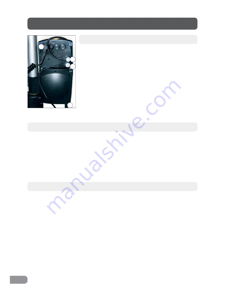
Remove the control box cover to make the connections as
described below. Use a screwdriver or similar; refer to the
special labels on the control box. NOTE! Make sure that
plugs are connected to the correct sockets otherwise the
actuators may be damaged.
1. Socket for the raise/lower actuator. NOTE! Make sure
that plugs are connected to the correct sockets
otherwise the actuators may be damaged.
2. Remote control socket.
3. Battery terminal socket.
4. Plug socket. NOTE! Plugs must ALWAYS be connected
to the control box for IP classification to be valid.
Battery charging
• Connect plug to 230V wall socket. Charging begins automatically and the battery
LED flashes green.
• Make sure the battery is fully charged before using for the first time. It takes around
24 h to fully charge the battery.
• We recommend that the battery plug be removed from the control box if the product
will be out of use for an extended period (more than three weeks). This eliminates the
risk of ruining the battery as the control box always uses a small quantity of electricity
even when the walker is not in use.
LED´s on control box and battery
• Control box – green light when power is available from battery/mains socket.
• Battery:
• The LED flashes green during charging.
• The LED shows a constant green light when the battery is fully charged.
• When the battery is in normal state/in operation, the LED flashes green at regular
intervals of – 0.5 s ON, 4 s OFF.
• When the battery requires charging (remaining charge less than 25%) the LED
flashes orange/red at regular intervals of – 0.5 s ON, 4 s OFF.
NOTE!
The battery has an in-built function that automatically switches it off when
remaining charge is less than 20%. The LED is then extinguished. The battery must
now be fully charged before the electronics can be used again.
1
2
3
4
Other instructions – T-Motion


