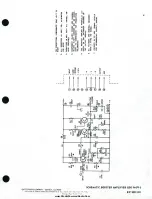
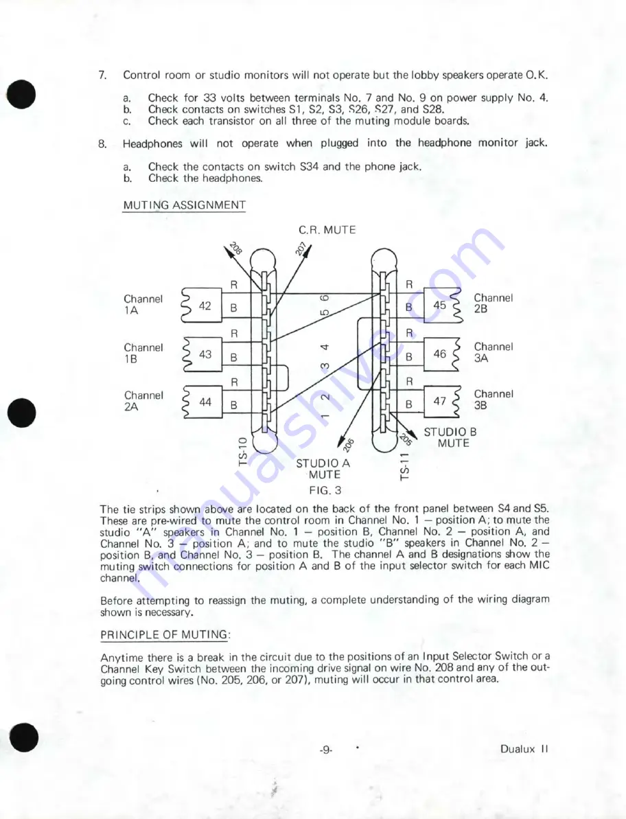
Summary of Contents for DUALUX II M6542-A

Page 1: ...www SteamPoweredRadio Com TECHNICAL MANUAL s HARRIS CORPORATION Broadcast Group P O Box 4290 Quincy Illinois 62305 4290...

Page 2: ...www SteamPoweredRadio Com 8881089 001 INSTRUCTION BOOK FOR DUALUX II GATES M6542 A MONO STEREO TRANSISTOR CONSOLE GATES RADIO COMPANY QUINCY ILLINOIS...

Page 3: ...rom the use of improperly trained or inexperienced personnel performing such tasks During installation and operation of this equipment local building codes and fire protection standards must be observ...

Page 4: ...OT BREATHING BEGIN ARTIFICIAL BREATHING TILT HEAD PINCH NOSTRILS MAKE AIRTIGHT SEAL 4 QUICK FULL BREATHS REMEMBER MOUTH TO MOUTH RESUSCITATION MUST BE COl IENCED AS SOON AS POSSIBLE DEPRESS STERNUM 1...

Page 5: ...quickly as possible e If arms or legs are affected keep them elevated NOTE If medical help will not be available within an hour and the victim is conscious and not vomiting give him a weak solution o...

Page 6: ...ent has a grounded connection wire an isolating trans former must be used between that equipment and the console A final ohmmeter check is recommended After all system connections are made temporarily...

Page 7: ...a cleaning agent WARNING DO NOT use carbon tetrachloride It causes noise and the fumes may cause injury to personnel 3 Use a soft clean pencil eraser to remove spots or noisy areas not cleaned in Ste...

Page 8: ...onnections to Console 2 4 Output Connections to Console 3 OPERATIONS 4 a Master Gain Adjustment 5 b Cue Intercom System 5 MODE Switch Operations 6 MAINTENANCE 8 Troubleshooting 8 Troubleshooting Guide...

Page 9: ...lar program Line Out Gain Response Distortion Noise MONITOR CIRCUITS Gain Response Distortion POWER REQUIREMENTS Primary Power MECHANICAL SPECIFICATIONS Console Transformer Panel 60 dB 2 dB at 1 000 H...

Page 10: ...e to the user A selector switch is provided for AM FM CUE and NET monitoring In addition a stereo headphone jack is located on the right end of the console and connected to the output of the monitor a...

Page 11: ...troy this system A shield ground buss is provided beside both the input and output terminal blocks of the console All incoming and outgoing shields must be connected to these busses C INSTALLATION PRO...

Page 12: ...utput an isolation transformer such as Gates A 21 must be used Correct phase relationship is maintained within this console for stereo program ming It is therefore up to the installer to make certain...

Page 13: ...able or tape cannot be switched into mixer No 5 if it is already switched into mixer No 4 This prevents loading the turntable or tape output by paralleling it into two console inputs Cueina facilities...

Page 14: ...alancing procedure is completed the switch should be returned to the operate position b Cue Intercom System The controls are located on the lower center section of the panel The cue intercom input sel...

Page 15: ...AUTO FM AM AUTO STER SCA PGMS PGMS MOOE 3 Combined Programming from AM AM FM 0 LINE LINE 0 STEREO I I I SCA GEN ON ON AM FM AUTO FM AM AUTO STER SCA PGMS PGMS MODE 4 Combined Programming from FM Ster...

Page 16: ...ON GEN ON AM FM AUTO FM AM AUTO STER SCA PGMS PGMS MODE 8 FM STereo with AM Automation AM FM LINE LINE 0 STEAEOI SCA ON GEN ON AM FM AUTO FM AM AUTO STER SCA PGMS PGMS MODE 9 AM Auto FM Mono and SCA A...

Page 17: ...No 5 of the booster board and terminals No 3 and No of the output board in the program amps 2 No signal can be measured on any one of the program output lines but indication can be seen on thP VU met...

Page 18: ...the back of the front panel between S4 and S5 These are pre wired to mute the control room in Channel No 1 position A to mute the studio A speakers in Channel No 1 position B Channel No 2 position A...

Page 19: ...ng if the channel is not on the air each microphone selector switch is in parallel with the AM FM program selector switch As soon as this switch is placed in either the AM or FM position it opens and...

Page 20: ...MUTING SCHEMATIC A M S S i B P S S N 0 f 44 10 0 11 12 CH 2 AM O S27 6 f OFF FMO Ml KE SELECTOR SWITCH CONDITION CHANNEL 1 B CHANNEL 2 B CHANNEL 3 B FIG 4 A M s s i B P S S f 46 10 0 11 12 CH 3 AMO S...

Page 21: ...R XFORMER PAD PAD PAD PAD 200OHM UNSOLDER UNSOL DER UNSOLDER OR OR OR OR Change Tl Red Yellow Red Yellow Red Yellow XFORMER XFORMER XFORMER XFORMER incoming wires from 1 3 to 1 2 3 Wire Wire Wire SOLD...

Page 22: ...AT5 Attenuator Dual 554 0280 000 24 V DC Plug In 150 300 ohm AT6 AT7 Attenuator 554 0182 000 ATS 150 300 ohm R F Choke 1 mH 494 0114 000 w cue AT9 Cue Gain Pot 550 0282 000 10K ohm W LS1 Cue Speaker 7...

Page 23: ...000 W5 1 Res 200ohm 540 0032 000 XFl Fuseholder 402 0024 000 W5 XF2 1 Res 390 ohm 540 0039 000 W5 2 Res 3300 ohm 540 0061 000 W5 XKl Relay Socket 404 0160 000 S1 S2 Lever Sw 602 0007 000 S4 thru 4 Po...

Page 24: ...ansistor Socket 404 0066 000 C10 Cap 470 pF 1 kV 516 0043 000 XO3 XO4 Transipad 404 0198 000 Cl 1 Cap 01 uF 600 V 516 0080 000 C12 C13 Cap 002 uF 1 kV 516 0063 000 21 22 Ferrite Bead 414 0087 000 01 0...

Page 25: ...es 3900 ohm 540 0063 000 CB Cap 1 uF 75 V 516 0357 000 W5 C9 Cap35uF 50V 522 0257 000 R21 Res 15 ohm 540 0005 000 W5 C10 Cap 2500pF 500 0879 000 500V 5 R22 Same as R7 C11 Cap 500 pF 1 kV 516 0045 000...

Page 26: ...07 000 W5 R4 Res 68 ohm 540 1110 000 W5 A5 Res 1300 ohm 540 0052 000 W5 R6 Res 9100 ohm 540 0072 000 W5 A7 Aes5600ohm 540 0067 000 W5 R8 Res 100 ohm 540 1102 000 W5 R9 Res 1000 ohm 540 0049 000 W5 Rl0...

Page 27: ...2 Transistor 40310 380 0062 000 Al Res 1500 ohm 540 0470 000 1 W 10 Comp 03 Transistor 40319 380 0044 000 R2 Res 50 ohm 542 1067 000 04 Transistor 2N697 380 0042 000 5W 10 R3 Res 2ohm 542 1105 000 20W...

Page 28: ...2500 ohm 574 0140 000 K3 T1 T2 Power Transformer 472 0570 000 T3 T4 Power Transformer 472 0569 000 TB1 TB2 Terminal Board 614 0010 000 7 SYMBOL DESCRIPTION XFl thru XF4 Fuseholder GATES PART NO 402 0...

Page 29: ...540 0050 000 R15 W5 R2 R7 Res 1500 ohm 540 0053 000 R16 W5 R3 R6 Res 47 Kohm 540 0089 000 W 5 R4 Res 8200 ohm 540 0071 000 W 5 R5 R14 Res 3000 ohm 540 0060 000 W 5 R9 R10 Res 100 ohm 540 0025 000 R12...

Page 30: ...3 dB loss ohms ohms ohms 12 min 510 6 8 160 15 510 51 110 20 560 100 62 25 560 120 33 Rl R2 INPUT R3 R101 R102 NOTE This chart may be used for H pads by halving R 1 and making R 101 equal to halfof R...

Page 31: ...er Loading The load impedance of the moni tor amplifier is 8 ohms Speaker loads of 4 to 16 ohms may be used Loading the amplifier low er than 4 ohms may damage the unit Some suggested loads are listed...

Page 32: ...NOISE RESIST ORS 5 R9 SELECTED FOR TOTAL AMPLIFI ER CURRENT TO BE 10 18 MA NO SiCNAL PARTS REPL ACEMENT MAY REQUIRE CHANGE Of R9 VALUE D C VOLTAG ES ARE N O INAL I E ASUREO II TH A VTVM N O SI GNU 7 V...

Page 33: ...ONOITS SIDE LEFT TO RIGHT 2 ALL RESISTORS 1 2 WATT 5 11 DENOTES LOW NOISE 3 CAPlll CITORS IN MFD WITH D C RATING UN L ESS SPECIFIED 4 COMPOtlENT VALUES SHOWN ARE NOMINAL VALUES SLIGHT CHANGES MAY BE N...

Page 34: ...A RS l 11 tASuUl J1 T lffVH o 2MV S lG illR 4 1V ll 14 V 3ov Sl f LY 4 RIO AND Rl2 RE FAC l t RY R2 SE I EC TtC R R 40 tM Rq soo R l t R8 1 30 4 iviv 14 1V 5 RI tR t 19 J l IO Q4 40 _ltf YHE 1 T l ll...

Page 35: ...TORS IN MFO WITH D C RATING CvMPONENT VALUES Sl OWN ARE NOMINAL VALUES SLIGHT CHANGES MAY BE NECESSARY TO COMPENSATE FOR PROOUCTION TOLEf ANf ES 4 C2 IS EXTERNALLY MOUHTEO V 0 0 8 9 5 0 6 I 1_c2 T 100...

Page 36: ...VOLTAGES TAKEN WITH VOM 20000 1 PER VOLT SUPPLY LOADED FOR 7110 MA L 1 1N VOLTAGE 12bv I LLOW 101 o VARIATION 5 IOOO U j jl CAP IS EXTERNAl l Y MOUNTED 4 V o I l _ IOOOUF _ T _ 75 V I I l Q CR I N 7...

Page 37: ...I _ _ 1 I 1NPUT 33V I I COMMON 1 I NOTES I SINGLE SOLID STATE MUTING MODULE IS COMPOSED OF ONE BOARD IN ONE EXTRUSION ASS 1 Y M6553A 2 DOUBLE SOLID STATE MUTING MODULE IS COMPOSED OF TWO BOARDS IN ON...

Page 38: ...c_ IC Oz r co lt j r c N N GATES RADIO COMPANY QUINCY ILLINOIS A OI YISf fl 0 W AIIUUS f riiT illTYPf t Ool ONAltOH GI IN N N 0 c fO 0 0 0 J z C IL J z 0 0 0 z 0 I u C IL 0 0 I z c 0 a i z 0 r e IL 0...

Page 39: ...j 0 llt c v z GATES RADIO COMPANY QUINCY ILLINOIS A 01Yt 10N OF HARRIS IHTERTYPE COAPOAAT IOH s 8 QI e fl 0 0 t i s I J n8 QI c s s 111 8 ttS I J l ii 0 1 SCH EMATIC DRIVERS FORSS MUTING AND RELAY DUA...

Page 40: ...l L MON C H j fL I Ml ll M t Vt NPUTS C CO c M l 1 lT LtV L ATt li K d 91 1 1 I 01 r o l vu A 1 f 1 AVTO J M A JTO a11 1ttc A qqqcfiqqqq Sll A 0 t f r 1 LE ET M9 1TQR MPPlllf us 1 01 11 C I I I I I I...

Page 41: ...C r t EE E I i M Q c l ll b Ai ou rPvr 2 _ j o I 1 r l 0 W 0 2t WOOA L t ru L 1 i w e 7 a I H l M 0 J P T 4 r _ t b c J I O 70 4 i t T on __ _ __ _l i _ L 1 1 I r 2 0 2 0 o l7iS T t 4 i 4 3 l f _ QIIL...

Page 42: ...ljl P _ A 8 r 0 z C 0 I 2 I 5 12 I 0 14 L 1 6 17 18 I 19 CABLE FIOUTIHC YO TEP MIW 8L0 5 E CA8t COlfNf CT IN COMING CIRCUIT SHIE 0S i CA Ell ET GAOUNO 0 C I I I 0 I I I 0 I T8 3 r I I I I 4 t I PO I E...

Reviews: