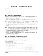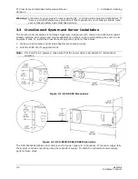
3 – Installation & Wiring
T1 CrossConnect Installation & Operation Manual
Version 2
GatesAir
3-3
Intraplex Products
1.
Remove the front cover of CrossConnect shelf by removing the Phillips screw in the front cover to
the right of the Power/Normal/Alert/Alarm indicator lights.
2.
Insert the second power supply into the redundant supply slot on the front. (Its indicator lights
turn on identically to those on the main supply.)
3.
Replace the front cover.
Power supply modules require no special setup. As long as they are plugged into their slots and
system power is applied, they are operating. If a shelf is equipped with two power supplies (main and
redundant) and one of the supplies fails, it may be removed and a new supply inserted without
powering down the system.
3.4 Wiring
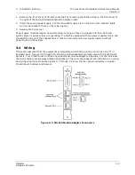
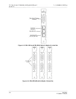
This section assumes that the equipment is completely wired before placing into service any T1 or
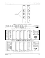
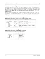
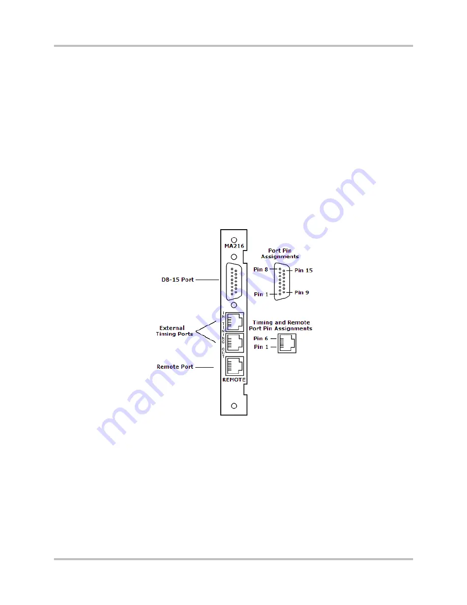
payload circuit. Figures 3-3 through 3-6 show the module adapters typically used with CrossConnect
products. Your CrossConnect unit may have additional module adapters. Appendix A of the individual
channel module manuals gives detailed descriptions of each module adapter and information on wiring
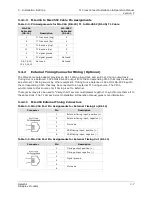
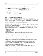
and configuring those products. Figures 3-7 through 3-9 show the rear panel connectors on typical
CrossConnect Systems and Servers.
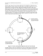
Figure 3-3. MA-216 Module Adapter Connectors
Summary of Contents for Intraplex T1 DCS-9530 CrossConnect System
Page 2: ......

