4 – Mapping Basics
T1 CrossConnect Installation & Operation Manual
Version 2
GatesAir
4-11
Intraplex Products
●
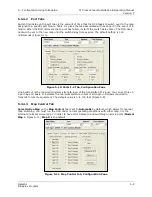
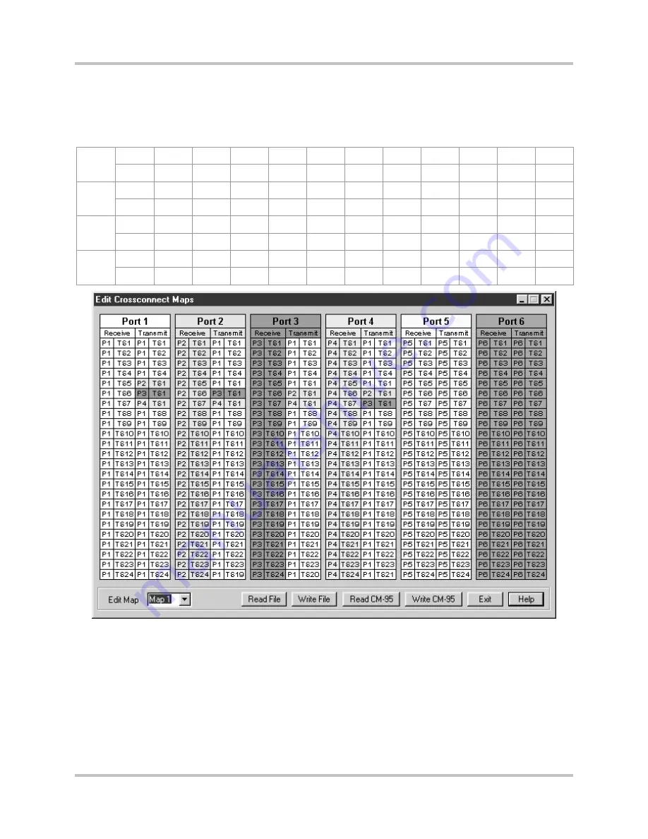
In time slot 5, port 3 receives data from port 1 time slot 1; in time slot 6, port 3 receives data
from port 2 time slot 1; in time slot 7, port 3 receives data from port 4 time slot 1.
●
In time slot 5, port 4 receives data from port 1 time slot 1; in time slot 6, port 4 receives data
from port 2 time slot 1; in time slot 7, port 4 receives data from port 3 time slot 1.
Table 4-7. ISiCL Map for Complex Interchange Configuration
P
o
rt
1
1,1
1,2
1,3
1,4
2,1
3,1
4,1
1,8
1,9
1,10
1,11
1,12
1,13
1,14
1,15
1,16
1,17
1,18
1,19
1,20
1,21
1,22
1,23
1,24
P
o
rt
2
1,1
1,2
1,3
1,4
1,1
3,1
4,1
1,8
1,9
1,10
1,11
1,12
1,13
1,14
1,15
1,16
1,17
1,18
1,19
1,20
1,21
1,22
1,23
1,24
P
o
rt
3
1,1
1,2
1,3
1,4
1,1
2,1
4,1
1,8
1,9
1,10
1,11
1,12
1,13
1,14
1,15
1,16
1,17
1,18
1,19
1,20
1,21
1,22
1,23
1,24
P
o
rt
4
1,1
1,2
1,3
1,4
1,1
2,1
3,1
1,8
1,9
1,10
1,11
1,12
1,13
1,14
1,15
1,16
1,17
1,18
1,19
1,20
1,21
1,22
1,23
1,24
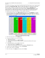
Figure 4-11. IntraGuide Map for Complex Interchange Configuration
4.8 Point-to-Point Configuration Mapping
In point-to-point protection switching applications, when a failure, or degradation of a primary T1 line,
is detected, both DCS nodes switch to the backup path. In Figure 4-17, the primary path appears as a
thick line, and the backup one as a thin line.
Summary of Contents for Intraplex T1 DCS-9530 CrossConnect System
Page 2: ......


