background image

18

Case Access

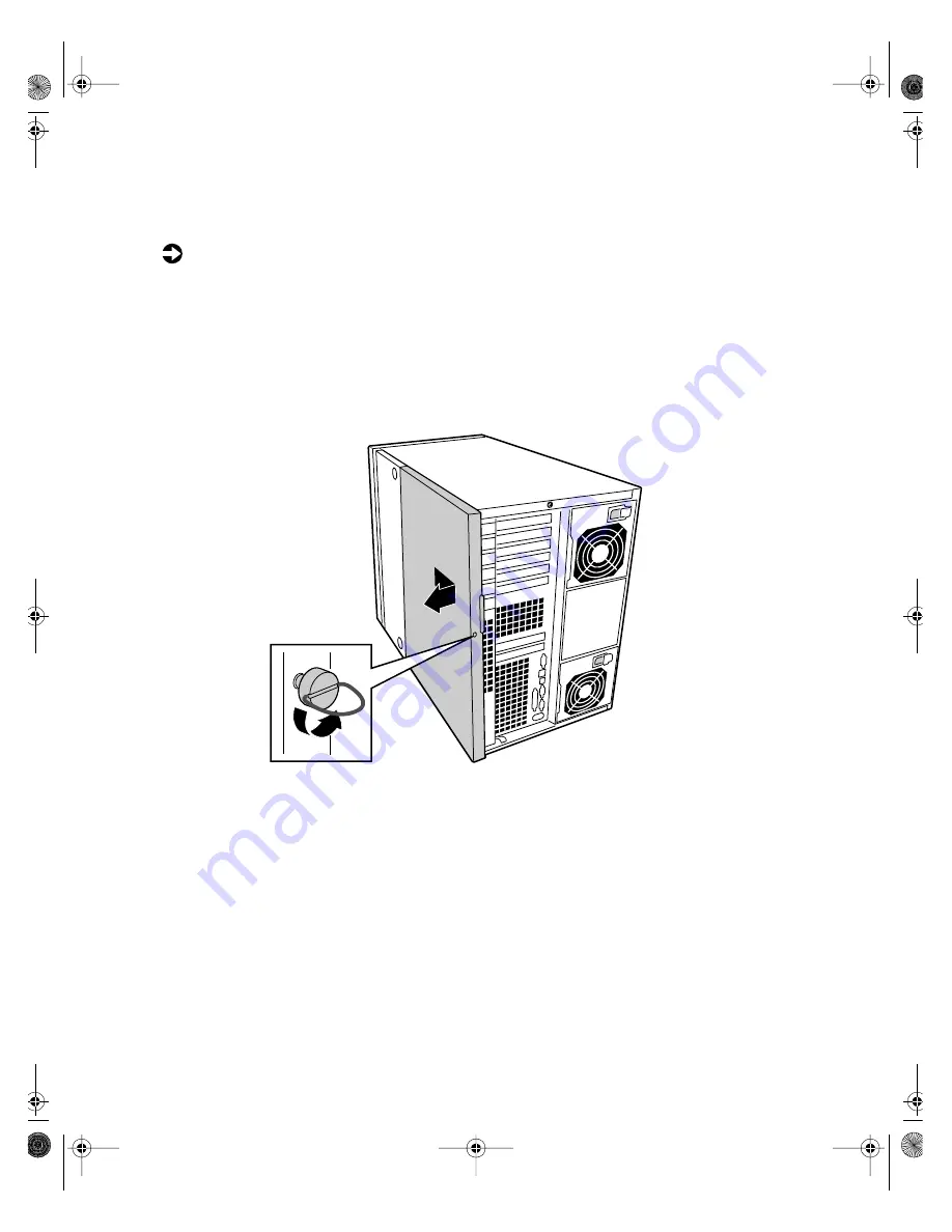
Removing the side panels

 To remove the right side access panels:

1

Turn off the computer and disconnect all power cords.

2

Loosen the thumbscrew (captive) on the back of the back access panel 
and unlock the chassis lock (if applicable).

3

Slide the back access panel approximately 3/4-inch toward the back of 
the system, disengaging the retaining tabs on the top and bottom edges 
of the panel from the slots on the chassis.

4

Grasping the front and back edges of the panel, pull the panel out and 
away from the chassis.

05895.book Page 18 Thursday, May 11, 2000 1:11 PM

Summary of Contents for 8400

Page 1: ...8400 Server System Manual A MAN US 8400 SYS GDE R0 5 00 ...

Page 2: ...5 Preventing static electricity discharge 15 Opening the case 17 Removing the side panels 18 Opening the chassis bays 20 Closing the case 22 Closing the chassis bays 22 Replacing the side panels 23 4 Replacing and Adding System Components 25 Replacing or adding drives 25 Preparing to replace or add a drive 25 Drive cabling considerations 27 The 3 5 inch diskette drive 28 The 5 25 inch device 30 SC...

Page 3: ...problems 79 Surge suppressors 79 Line conditioners 80 Uninterruptible power supplies 80 Maintaining and managing your hard drive 81 Hard drive maintenance utility 81 Hard drive management practices 82 Protecting your computer from viruses 84 System administration and control 85 Intel Server Control ISC 85 ManageX Event Manager 85 Direct Platform Control DPC Console 86 System security 86 System rec...

Page 4: ...oblems 96 Memory and processor problems 97 Modem problems 98 Peripheral adapter problems 99 Printer problems 101 System problems 103 Video problems 105 Error messages 108 A Safety and Regulatory Information 113 B Reference Data 129 Specifications 129 System specifications 129 Environmental specifications 130 Index 131 05895 book Page iii Thursday May 11 2000 1 11 PM ...

Page 5: ...iv 05895 book Page iv Thursday May 11 2000 1 11 PM ...

Page 6: ... DEL A plus sign means to press the keys at the same time Setup Commands to be entered options to select and messages that appear on your monitor are printed in bold User s Guide Names of publications are printed in italic Viewpoint All references to front rear left or right on the computer are based on the computer being in a normal upright position as viewed from the front 05895 book Page v Thur...

Page 7: ...portant informs you of special circumstances Caution A caution warns you of possible damage to equipment or loss of data Warning A warning indicates the possibility of personal injury 05895 book Page vi Thursday May 11 2000 1 11 PM ...

Page 8: ...ystem or other Gateway products Some types of information you can access are Hardware driver and program updates Technical tips Service agreement information Technical documents and component information Frequently asked questions FAQs Documentation for peripherals or optional components Online technical support 05895 book Page vii Thursday May 11 2000 1 11 PM ...

Page 9: ...viii 05895 book Page viii Thursday May 11 2000 1 11 PM ...

Page 10: ...rated Adaptec AIC 7899 Dual Channel Ultra Ultra II Ultra 160 Ultra 3 SCSI controller Integrated Adaptec AIC 7880 narrow wide Ultra SCSI controller Integrated ATI Rage IIC video controller with 2 MB of SDRAM Six full length hot pluggable PCI slots and two half length PCI slots Baseboard Management Controller BMC hardware management ATX form factor system board and pedestal chassis convertable to ra...

Page 11: ...ally accessible drives Door Lock controls access to the external controls and externally accessible drives Drive cage door protects the hard drive cages from tampering Diskette drive Power button CD drive Reset button Door lock Door open Front panel LEDs Drive cage door open Sleep button SCSI hard drive cage A SCSI hard drive cage B NMI reset switch 05895 book Page 2 Thursday May 11 2000 1 11 PM ...

Page 12: ... a critical non recoverable cooling problem and blinking yellow when system has a non critical over temperature or low fan speed condition Hard drive cages hold five 1 inch hot swappable SCSI hard drives each NMI Non Masking Interrupt reset switch is used by technicians to debug a server having problems Power button turns the computer on and off It also enables sleep mode in some operating systems...

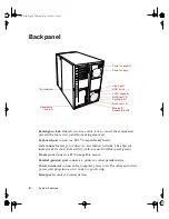
Page 13: ...llow and 100 Mbit speed green Mouse port connects a PS 2 compatible mouse Parallel printer port connects a printer or other parallel device Power connector connects the computer power cord The other end of the power cord plugs into an AC outlet or power strip Serial ports connect to serial devices Serial port A Mouse Keyboard ports Serial port B Power connector LAN connector USB ports Parallel por...

Page 14: ... connect external Plug and Play devices that are automatically configured when they are plugged into the computer through one of these ports USB keyboards and mice are not supported use only PS 2 versions Video port connects the monitor interface cable 05895 book Page 5 Thursday May 11 2000 1 11 PM ...

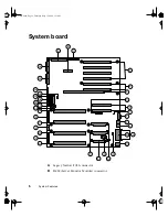
Page 15: ...ures System board A Legacy Narrow SCSI connector B SMM Server Monitor Module connector A C D I J K L M N O P Q V W S X E G R Y Z AA B F H T U AB AC AD AE AF AG AH AI AJ 05895 book Page 6 Thursday May 11 2000 1 11 PM ...

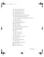
Page 16: ...tor K External USB ports 2 L RJ 45 Ethernet LAN connector M Parallel connector N Serial connectors O Keyboard and PS 2 Mouse connectors P Internal USB connector Q Processor 2 VRM slot R Battery S Processor 4 VRM slot T Processor 3 VRM slot U Processor 4 slot V Main ATX Power 1 connector W Processor 3 slot X Auxiliary Power connector Y Processor 2 slot Z Main ATX Power 2 connector AA Processor 1 sl...

Page 17: ... connector AF Front Panel connector AG IMB Intra Module Bus connector AH Configuration Jumper J9F2 Pins 1 3 CMOS Clear Pins 5 7 Password Clear Pins 9 11 Boot Option AI Ultra 160 SCSI A connector AJ Ultra 160 SCSI B connector 05895 book Page 8 Thursday May 11 2000 1 11 PM ...

Page 18: ...p helps protect against AC power fluctuations Protect your system from extreme temperature and humidity Do not expose your system to direct sunlight heater ducts or other heat generating objects Keep your computer away from equipment that generates magnetic fields such as unshielded stereo speakers Even a telephone placed too close to the computer may cause interference Plug the computer into a wa...

Page 19: ...d that the power strip is turned on To start the system 1 If you have connected the system components to a power strip make sure all the system components are turned off then turn on the power strip 2 Turn on the monitor Caution Make sure your computer and peripherals are turned off and unplugged from the power outlet when you connect peripherals to the computer or you might damage the computer or...

Page 20: ...n Make sure the monitor is connected to the computer plugged into the power strip or AC outlet and turned on You may also need to adjust the brightness and contrast controls on the monitor Understanding the Power On Self Test When you turn on your computer the power on self test POST routine checks the system memory and components If POST finds any problems the system displays error messages Write...

Page 21: ...he appropriate text boxes When you have finished typing the information continue by clicking Next 3 Continue following the instructions and selecting options in the start up wizard dialog boxes clicking Next to move through the dialog boxes until the wizard tells you to restart your computer If you need to return to the previous dialog box to change any of your entries click Back 4 Restart your sy...

Page 22: ...uter turn off the computer by pressing the power button 3 Turn off the monitor and peripherals Warning When you turn the computer off by pressing the power button some electric current still flows through the computer Before opening the computer case or connecting or removing any peripherals turn off the computer then unplug the power cord and modem cord if installed or you may get an electric sho...

Page 23: ...ens that lets you to close a program that is not responding 2 Click Task Manager then select the program that is not responding 3 Close the program by clicking End Task 4 If the computer does not respond press the reset button to restart the computer As a part of the regular startup process a program to check the disk status runs automatically When the checks are finished Windows starts Important ...

Page 24: ...charge 1 Wear a grounding wrist strap available at most electronics stores 2 Turn off the computer power 3 Touch a bare metal surface on the back of the computer 4 Unplug all power cords from AC outlets and disconnect the modem cable if installed Caution Static electricity can permanently damage electronic components in your computer Prevent electrostatic damage to your computer by following stati...

Page 25: ...nly when you are ready to use them Do not lay parts on the outside of an antistatic bag or container because only the inside provides antistatic protection Always hold cards by their edges and their metal mounting brackets Avoid touching components on the cards and the edge connectors that connect to expansion slots Never slide cards or other parts over any surface 05895 book Page 16 Thursday May ...

Page 26: ... avoiding static electricity damage Only qualified personnel should open the system for maintenance If you are qualified to maintain the system yourself make sure you are properly grounded before opening the system chassis Important All references to front rear left or right on the computer are based on the computer being in a normal upright position as viewed from the front Warning Avoid exposure...

Page 27: ...back access panel and unlock the chassis lock if applicable 3 Slide the back access panel approximately 3 4 inch toward the back of the system disengaging the retaining tabs on the top and bottom edges of the panel from the slots on the chassis 4 Grasping the front and back edges of the panel pull the panel out and away from the chassis 05895 book Page 18 Thursday May 11 2000 1 11 PM ...

Page 28: ...e 19 5 Loosen the two captive screws securing the front access panel to the chassis 6 Slide the front access panel to the back and pull outward to remove Captive screws 05895 book Page 19 Thursday May 11 2000 1 11 PM ...

Page 29: ...onics bays 1 Observe the safety and ESD precautions in Preventing static electricity discharge on page 15 2 Turn off all peripheral devices connected to the system 3 Turn off the system power by using the power on off switch on the front panel and unplugging all AC power cords 4 Label and disconnect all peripheral cables attached to the I O panel on the back of the system 5 Remove the access panel...

Page 30: ...from the main chassis until it stops 9 If necessary completely remove the drive bay and electronics bay by rotating the bays outward until the two pins that function as hinges for the bays slide out of their slots Set the bays aside Caution You must disconnect all cabling to the electronics bay before rotating removing the bays Failure to do so can result in serious damage to system components Saf...

Page 31: ...components to ensure that you do not pinch or twist any of the cables or components To close the drive and electronics bays 1 Verify that all internal components are fully installed and secured 2 Swing the electronics bay closed 3 Attach any cables to the electronics bay components 4 Press down on the tab on the top of the drive bay to release it and swing it closed 5 Replace the access covers and...

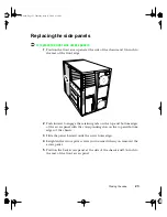
Page 32: ...ning tabs on the top and bottom edges of the access panel with the corresponding slots on the top and bottom edges of the chassis 3 Slide the panel forward until the screw holes align 4 Retighten the two captive screws you loosened when you removed the access panel 5 Position the back access panel at the side of the chassis and 3 4 inch to the rear of the front access panel 05895 book Page 23 Thur...

Page 33: ... bottom edges of the panel with the corresponding slots on the top and bottom edges of the chassis 7 Slide the panel forward until it lines up with the front access panel 8 Tighten the thumbscrew and lock the case if necessary 05895 book Page 24 Thursday May 11 2000 1 11 PM ...

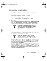
Page 34: ...ter You can add drives of the following types Ten additional 3 5 inch SCA 2 SCSI hard drives with two hard drive cage assemblies installed standard configuration The integrated dual channel Ultra 160 Adaptec SCSI controller will support as many as 30 drives Two additional 5 25 inch devices or two additional 3 5 inch devices with 5 25 inch drive rail adaptors 05895 book Page 25 Thursday May 11 2000...

Page 35: ...you install the drive IDE drives can be configured as single master or slave IDE CD drives can be configured as master or slave Configure the drives by using the drive select jumpers located on the drives If only one drive is attached to a controller cable configure the drive as master if it is a CD drive If two drives of any type are attached to the cable configure one as master and one as slave ...

Page 36: ...SCSI cable Hard drives usually provide active termination while SCSI CD ROM drives do not The SCSI backplane on the hard drive cage provides active termination for the SCSI drives connected to the backplane In general install legacy devices in the 5 25 inch drive bay and connect them to the legacy SCSI cable Ultra Ultra 2 and Ultra 160 Ultra 3 devices are normally hard drives Connect them to the S...

Page 37: ...Opening the case on page 17 3 Remove the fans see Replacing the system fans on page 67 and foam fan carrier from the drive bay 4 Disconnect the power and signal cables from the diskette drive The connectors are keyed for ease in reconnecting them to the drive 5 Remove and save the screw that secures the diskette drive mounting bracket to the side of the 5 25 inch drive bay 6 Slide the mounting bra...

Page 38: ...the new 3 5 inch diskette drive from its protective wrapper and place it component side up on an antistatic surface 11 Set any jumpers or switches according to the drive manufacturer s instructions 12 Place the drive into the mounting bracket by sliding the back of the drive into the bracket then lowering the mounting holes on the front of the drive onto the two retention pins in the front portion...

Page 39: ... Run the BIOS Setup utility to specify that the diskette drive is installed in the system The 5 25 inch device Three 5 25 inch half height bays provide space for tape backup CD or other removable media drives Either type of device IDE or SCSI can be installed in the 5 25 inch peripheral bays The system board only provides a single IDE connector and therefore only supports two IDE devices The legac...

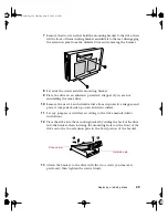
Page 40: ...queeze the rail tabs toward each other as you carefully slide the drive forward out of the bay and place it on an antistatic surface 7 Remove and save the four screws and two slide rails Tab on slide rail Slide rail Slide rail Tab on slide rail 05895 book Page 31 Thursday May 11 2000 1 11 PM ...

Page 41: ...E data cable up to 18 inches long 13 If the drive requires any other cables connect them 14 Close the drive bay making sure not to damage any data or power cables see Closing the chassis bays on page 22 15 Replace the access panels see Closing the case on page 22 16 Close the computer door To install a 5 25 inch device 1 Observe the safety and ESD precautions in Preventing static electricity disch...

Page 42: ...ve according to the drive manufacturer s instructions Important System EMI integrity and cooling are both protected by having drives installed in the bays or filler panels and EMI shields covering the bays When you install a drive save the panel and shield to reinstall in case you should later remove the drive and not reinstall one in the same bay Important Installing a DLT tape backup drive requi...

Page 43: ...ng IDE drive The system board has one IDE connector It can support an IDE data cable up to 18 inches long 11 If the drive requires any other cables connect them 12 Close the drive bay making sure not to damage any data or power cables see Closing the chassis bays on page 22 13 Replace the access panels see Closing the case on page 22 14 Close the computer door Caution The internal narrow SCSI inte...

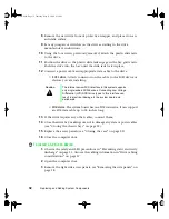
Page 44: ... a 5 25 inch device for illustration Remove and save the shield 5 Open the drive bay see Opening the chassis bays on page 20 to gain access to the back of the 5 25 inch drive bay 6 Remove the drive from its protective wrapper and place it on an antistatic surface 7 Set any jumpers or switches on the drive according to the drive manufacturer s instructions Important System EMI integrity and cooling...

Page 45: ...ctors on the cable to the SCSI device or devices you are installing IDE drive The system board has one IDE connector It can support an IDE data cable up to 18 inches long 12 If the drive requires any other cables connect them 13 Close the drive bay making sure not to damage any data or power cables see Closing the chassis bays on page 22 14 Replace the access panels see Closing the case on page 22...

Page 46: ... Installing a SCSI hard drive Before you can install a SCA 2 SCSI hard drive in the system you must mount it on a drive carrier to allow easy installation into the server To install a SCSI drive 1 Open the computer door 2 Open the metal door protecting the hard drive cages 3 Select the slot in the hard drive cage where you intend to install the new SCSI drive 4 Pull up on the bottom of the plastic...

Page 47: ... carrier so the latch is toward you and the rails are down 9 Place the drive in the drive carrier so the connector is to the rear of the drive carrier opposite the plastic latch and the drive label is up 10 Attach the drive to the drive carrier using the four screws previously removed 11 Holding the assembly by the drive carrier position it so that it engages the hard drive cage guide rails of the...

Page 48: ...ive on the far left The five LEDs and corresponding drives are numbered left to right zero through four When a green LED is on continuously indicating a bad drive you can hot swap replace the drive You do not need to shut the system down to hot swap a drive To hot swap a SCSI drive 1 Open the computer door 2 Open the metal door protecting the hard drive cages 3 Check the bank of green LEDs on the ...

Page 49: ...olding the assembly by the drive carrier position it so that it engages the hard drive cage guide rails of the open drive slot 9 Lift the plastic latch to the fully open position and firmly push the drive into the bay When the plastic latch engages the locking slot in the hard drive cage push down on it until it snaps into place 10 Close the metal door protecting the hard drive cages then close th...

Page 50: ...ur banks Each bank has four slots Bank 1 A1 A4 Bank 2 B1 B4 Bank 3 C1 C4 and Bank 4 D1 D4 When you are selecting and installing DIMMs keep the following in mind Memory must be installed by bank in groups of four in order beginning with Bank 1 A1 A4 All four DIMMs in a bank must be identical Only registered DIMMs should used No jumper settings are required for the memory size or type because the BI...

Page 51: ...rd s modem cord if installed and all other external peripheral devices 3 Remove the back access panel See Removing the side panels on page 18 and Preventing static electricity discharge on page 15 4 Loosen the captive screw securing the memory module retention bracket to the chassis then swing the retention bracket out from the chassis and remove it 1 2 3 05895 book Page 42 Thursday May 11 2000 1 ...

Page 52: ...m board and place it on a antistatic surface with the DIMM sockets facing up 6 Pull open the socket clamps on each side of the DIMM socket then lift the DIMM out of the socket Store the DIMM in an antistatic container Memory module System board 05895 book Page 43 Thursday May 11 2000 1 11 PM ...

Page 53: ...e DIMM 9 Repeat the process with the other three DIMMs in the bank 10 Reinstall the memory module card into its slot in the system board Make sure to align the card with the plastic guides on the chassis 11 Reinstall and secure the memory module retention bracket with the attached captive screw 12 Reinstall the back access panel following the instructions on page 23 13 Reconnect peripherals the mo...

Page 54: ...he DIMM in an antistatic container 5 Repeat the process with the other three DIMMs in the bank 6 Reinstall the memory module card into its slot in the system board Make sure to align the card with the plastic guides on the chassis 7 Reinstall and secure the memory module retaining bracket with the attached captive screw 8 Reinstall the back access panel following the instructions on page 23 9 Reco...

Page 55: ...he side panels on page 18 and Preventing static electricity discharge on page 15 4 To add a DIMM pull open the socket clamps on each side of the DIMM socket 5 Insert the new DIMM into the socket and align the two notches in the DIMM with the two notches in the DIMM socket Important DIMMs must be added or removed in banks of four see Replacing or adding memory on page 41 Installation must be done i...

Page 56: ...e bank 8 Reinstall the memory module card into its slot in the system board Make sure to align the card with the plastic guides on the chassis 9 Reinstall and secure the memory module retaining bracket with the attached captive screw 10 Reinstall the back access panel following the instructions on page 23 11 Reconnect peripherals the modem cord and the power cord s then turn on the system 05895 bo...

Page 57: ...ocessor order a processor upgrade kit from Gateway The kit includes the processor a heatsink and a VRM To replace a processor 1 Observe the safety and ESD precautions in Preventing static electricity discharge on page 15 2 Turn off the system and disconnect the power cord s modem cord if installed and all other external peripheral devices 3 Remove the back access panel See Removing the side panels...

Page 58: ...e the new processor from its antistatic container 11 Align the new processor with the processor slot note that the processor slot is keyed so the processor can only be installed one way and press firmly to install it 12 Reinstall the processor retention bracket onto the processor retention module 13 Replace the foam cover on the electronics bay 14 Reinstall and secure the memory module retaining b...

Page 59: ...nnect the power cord s modem cord if installed and all other external peripheral devices 3 Remove the back access panel See Removing the side panels on page 18 4 Loosen the captive screw securing the memory module retention bracket to the chassis then swing the retention bracket out from the chassis 5 Remove the foam cover from the lower electronics bay Do not remove the plastic air baffle attache...

Page 60: ...static container for future use 10 Remove the new processor from its antistatic container 11 Align the new processor with the processor slot note that the processor slot is keyed so the processor can only be installed one way and press firmly to install it 12 Reinstall the processor retention bracket onto the processor retention module using the screws you removed previously 05895 book Page 51 Thu...

Page 61: ...of the VRM 14 Replace the foam cover on the electronics bay 15 Reinstall the memory module retaining bracket and secure with the attached captive screw 16 Reinstall the back access panel following the instructions on page 23 17 Reconnect peripherals the modem cord and the power cord s then turn on the system 18 You must enable Processor Retest from the BIOS Setup utility whenever you replace or ad...

Page 62: ...e the back access panel See Removing the side panels on page 18 4 Locate an available slot appropriate to the type of card you are installing 64 bit 66 MHz or 64 bit 33 MHz full length PCI see System board on page 6 for locations 5 Remove the slot cover by gently pushing it out the back of the chassis 6 Press the center of the plastic card retainer then rotate it out of the way Important Expansion...

Page 63: ...rd is a full length card with a plastic stabilizer close the plastic rear retention latch to secure the other end of the card in place 11 Replace the back access panel 12 Reconnect the power cord s modem cord if installed and all other external peripheral devices 13 Restart the system and install drivers as necessary You may need to reconfigure your system after installing some expansion cards You...

Page 64: ...etention bracket and the foam cover on the lower electronics bay Do not remove the plastic air baffle attached to the foam cover 5 Locate an available half length slot 6 Remove the screw securing the slot cover in place then remove the cover 7 Set any jumpers on the card to the appropriate settings refer to your card documentation for jumper settings 8 Holding the card by its top edges firmly pres...

Page 65: ...nd Preventing static electricity discharge on page 15 2 Locate an available slot appropriate to the type of card you are installing 64 bit 66 MHz or 64 bit 33 MHz see System board on page 6 for locations 3 Remove the slot cover by gently pushing it out the back of the chassis 4 Press the center of the plastic card retainer then rotate it out of the way See To add a full length expansion card on pa...

Page 66: ...ngth card with a plastic stabilizer close the plastic retention latch to secure the other end of the card in place 10 Press the switch beside the LEDs to turn on the power to the PCI slot The LED will blink green for a few seconds then show steady green when the power is on 11 Replace the back access panel You may need to reconfigure your system after installing some expansion cards You may also n...

Page 67: ...e card is a full length card with a plastic stabilizer open the plastic retention latch to release the other end of the card 6 Holding the card by its top edges firmly pull the card from the expansion slot on the system board 7 If you are installing another card in the selected slot see To install a hot pluggable full length expansion card on page 56 If you are not installing another card place a ...

Page 68: ...nformation about the BIOS Setup utility program see Using the BIOS Setup Utility on page 71 3 Observe the safety and ESD precautions in Preventing static electricity discharge on page 15 Warning Danger of explosion if battery is incorrectly replaced Replace only with the same or equivalent type recommended by manufacturer Dispose of used batteries according to manufacturer s instructions Warnung E...

Page 69: ...attery is circular and has the positive pole mark on the top 9 Using a small flat bladed screwdriver carefully remove the battery from its socket on the system board 10 Press the new battery in the socket with the positive pole up Be sure you have pressed the battery down far enough for it to contact the base of the socket it should snap into place 11 Replace the VRM you removed 12 Close the case ...

Page 70: ...e system hardware manuals Correct any discrepancies Turn off the computer remove the cover and make sure that all cables inside the case are attached securely Also make sure that the colored cable edges are aligned correctly and that the connectors do not miss any pins Disconnect and reconnect the cables Close the case as described in Chapter 3 reconnect the modem and power cords then turn on the ...

Page 71: ...Do not remove the plastic air baffle attached to the foam cover 5 Place the chassis gently on its left side 6 Remove all expansion cards and the memory module card from the system board 7 Remove the processors the terminator cards and the processor retention brackets from the system board 8 Remove the plastic safety curtains between the PCI slots 9 Disconnect all cables from the system board inclu...

Page 72: ...ase 3 Replace the retention screws previously removed from the system board then tighten the screws 4 Reconnect the cables that you removed previously 5 Replace the plastic safety curtains between the PCI slots 6 Reinstall the processor retention brackets the processors and the terminator cards see Replacing or adding a processor on page 48 7 Reinstall the memory module card and other expansion ca...

Page 73: ...you to replace the indicated power supply prior to an actual failure To replace a hot swap power supply 1 Determine which power supply needs to be replaced based on the LED indicators on the top of each power supply If your system does not have three power supplies shut down your operating system and turn off the system power 2 Remove the four screws securing the power supply to the back of the ch...

Page 74: ...to the right 8 Plug the power cord into the new power supply 9 Verify that only the green power LED comes on 10 Align the new power supply with the opening left by the power supply you removed 11 With steady even pressure push the new power supply into the server until it seats firmly 12 Swing the power supply latch handle in and to the left to secure it 13 Replace the four screws you removed prev...

Page 75: ...fy that only the green power LED comes on 5 Align the new power supply with the opening left by the access cover you removed 6 With steady even pressure push the new power supply into the server until it seats firmly 7 Swing the power supply latch handle in and to the left to secure it 8 Replace the four screws you removed previously Important Gateway recommends that the top power supply be instal...

Page 76: ...tricity discharge on page 15 2 Determine which fan unit needs to be replaced The amber LED indicates faulty fan unit if ISC Intel Server Control is running 3 Grasp the fan unit firmly and pull straight out from the drive bay Warning Do not grip the fan by the sides of the fan bracket The fan blades may be in motion and may cut your fingers Use the holes in the top of the bracket as shown Warnung F...

Page 77: ...ide panels on page 18 and Preventing static electricity discharge on page 15 2 Determine where the fan unit needs to be placed large double fan units on the bottom and small single fan units on top 3 Grasp the fan unit and push inward seating the fan unit firmly in the drive bay 05895 book Page 68 Thursday May 11 2000 1 11 PM ...

Page 78: ...at the top left inside edge of the bezel depress the plastic retention tabs toward the outside edge of the bezel and pull the bezel out from the chassis slightly enough to keep the tabs from snapping back into place 4 Work your way around the bezel until all eight tabs three left one bottom two right and two top have been released then pull the bezel off the chassis Retention tabs Note Other reten...

Page 79: ...lastic retention tabs line up with the appropriate slots in the chassis 2 Press the bezel onto the chassis until the retention tabs snap into place 3 Align the door with the chassis just as it was aligned prior to removal 4 Insert the hinge pins 2 into the hinge pin sockets allowing the door to fall into place then close the door 05895 book Page 70 Thursday May 11 2000 1 11 PM ...

Page 80: ...en the Gateway logo screen appears during startup The Main BIOS Setup utility screen opens It may not look exactly like the screen shown below BIOS Setup Utility Main Advanced Security Server Boot Exit Item Specific Help System Time System Date Legacy Diskette A Legacy Diskette B Hard Disk Pre Delay Primary IDE Master Primary IDE Slave Processor Settings Language xx xx xx xx xx xxxx enabled auto E...

Page 81: ...pens a screen that lets you return all values to their default settings F10 opens a screen that lets you save all settings then exit the BIOS Setup utility The main screen has the following menu selections at the top of the screen Main gives you access to basic information and settings related to your system hardware and configuration Advanced gives you access to information and settings for syste...

Page 82: ...te To update the BIOS you need to perform the following tasks in sequence Create a bootable diskette Note the current BIOS settings Create the BIOS update diskette Update the BIOS Restore the BIOS settings Follow the detailed instructions for updating the BIOS that are included in the self extracting file that you can download from the technical support area of Gateway s Web site 05895 book Page 7...

Page 83: ...n page 6 for the location of the jumper The following table shows the settings required to perform those tasks Make sure you turn off the computer and unplug the power cord before moving the jumper Mode Jumper Setting Action When Set CMOS protected Pins 1 2 Normal operation Clear CMOS Pins 2 3 Causes computer to clear all BIOS settings and return to defaults Caution Moving the jumper while the pow...

Page 84: ...ngs required to perform this task Make sure you turn off the computer and unplug the power cord before moving the jumper Mode Jumper Setting Action When Set Protect Pins 5 6 Normal operation Clear Pins 6 7 Clears all passwords at bootup Caution Moving the jumper while the power is on can damage your computer Always turn off the computer and unplug the power cord s from the computer before changing...

Page 85: ...r the BIOS no image appears on your monitor To recover the BIOS 1 Turn off the system and disconnect the power cord modem cord if installed and all external peripheral devices 2 Remove the left side cover panel See Removing the side panels on page 18 and Preventing static electricity discharge on page 15 3 Remove the jumper from pins 9 10 of jumper J9F2 see System board on page 6 for location and ...

Page 86: ...nels on page 18 and Preventing static electricity discharge on page 15 8 Place the jumper back on pins 9 10 of jumper J9F2 9 Close the case reconnect the cords then turn on the computer 10 Enter the BIOS Setup utility by pressing F2 when the Gateway Logo screen appears 11 Once in BIOS Setup utility go to the appropriate tabs and select any BIOS fields you want to change then reenter the values you...

Page 87: ...78 Using the BIOS Setup Utility 05895 book Page 78 Thursday May 11 2000 1 11 PM ...

Page 88: ...loss or system damage Protect your computer and peripherals by connecting them to a surge suppressor which will absorb voltage surges and prevent them from reaching your computer When purchasing a surge suppressor Make sure the surge suppressor meets the appropriate product safety certification for your location such as Underwriters Laboratories UL Check the maximum amount of voltage the suppresso...

Page 89: ...s include more line noise than normal Line noise can also be a problem if your system is located near or shares a circuit with a device that causes electromagnetic interference such as a television or a motor Some surge suppressors and uninterruptible power supplies include simple line conditioning capabilities Uninterruptible power supplies Use a standby uninterruptible power supply UPS to protec...

Page 90: ... lost allocation unit is a group of sectors that has lost its place in the table that the operating system uses to locate files Check Disk checks the hard drive for bad sectors or lost allocation units and lets you fix them Use Check Disk from once a week to once a month depending on how often you use your system Also use Check Disk if you have any hard drive problems To use Check Disk 1 Double cl...

Page 91: ...ties The drive properties window opens The General tab shows you the available and used space on the drive Backing up files Regularly backing up your files protects you from losing data and lets you keep fewer files on your hard drive Back up old files to a large capacity disk drive or tape drive and delete the files from your hard drive You can use the software that came with your tape backup dri...

Page 92: ...ary Internet files on your hard drive in a memory cache and a disk cache Files in the memory cache are removed when you turn off your computer Files are saved in the disk cache until the space designated for the cache is full See your browser s Help files for instructions on emptying the disk cache You can save space on the hard drive by decreasing the size of the Internet file disk cache See your...

Page 93: ...ertain date or time Protect your computer from viruses by Using an anti virus program to check files and programs that are on diskettes attached to e mail messages or downloaded from the Internet After you run the anti virus program you can back up your files to diskettes a separate hard drive or a high capacity storage drive Keeping your anti virus program updated Obtaining all software from repu...

Page 94: ...variances in a number of ways from an entry in the event log to a displayed message or audio alarm or even a complete server shutdown ISC can also provide a system hardware inventory SCSI controller status LAN adapter status and BIOS and system slot information Additional information about Intel Server Control can be found under Documentation on the Server Companion CD which came with your system ...

Page 95: ...r both cover panels When an access cover is opened the switch transmits an alarm signal to the system board where server management software processes the signal You can program a response to an intrusion for example the system may power down or lock the keyboard Software locks through the BIOS Setup utility The Security tab in the BIOS see About the BIOS Setup utility on page 71 provides several ...

Page 96: ...e and enable the secure boot mode in the BIOS When secure mode is in effect you Can boot the system and run the operating system but you must enter the user password to use the keyboard or mouse Cannot turn off system power or reset the system from the front panel switches Taking the system out of secure mode does not change the state of system power That is if you press and release the power swit...

Page 97: ...cts a CD in the CD drive or a diskette in drive A it requests a password When you enter the password the system boots from CD or diskette and disables secure mode If you have not installed a CD drive or if there is no CD in the drive or diskette in drive A the system boots from drive C and automatically enters secure mode All enabled secure mode features go into effect at bootup To leave secure mo...

Page 98: ...e Password on Boot option using the BIOS Setup utility Once set passwords can be disabled by deleting the password or by changing the Clear Password jumper To change the jumper see Setting the system board jumpers on page 74 Boot without keyboard The system can boot with or without a keyboard During POST and before the system boots the BIOS automatically detects and tests the keyboard if present a...

Page 99: ...m When you set up Windows NT you are prompted to create a startup diskette If you did not choose to create a startup diskette at that time you may create one later by running the Windows NT upgrade installation program This process is started by going to the DOS Command Prompt changing to the C I386 subdirectory and typing winnt32 ox Press ENTER and follow the prompts Using your Server Companion C...

Page 100: ...d turn your mouse right side up The roller ball should drop into your hand If it does not gently shake the mouse until the ball drops out of the socket 4 Use adhesive tape to pick up any dust or lint on the surface of the ball 5 Wipe away dirt or lint inside the ball socket with a lint free cloth You can also blow into the socket to remove dirt and lint Use a cotton swab dipped in isopropyl alcoho...

Page 101: ...nd monitor cases Always turn off the computer and other peripherals before cleaning any components Use a damp lint free cloth to clean the computer case monitor case keyboard speakers and other parts of your system Avoid abrasive or solvent cleaners because they can damage the finish on your components Your computer is cooled by air drawn in through the vents on the chassis and blown out through t...

Page 102: ...erate correctly re read the instructions for the procedures you have performed If an error occurs within a program consult the documentation supplied with the program This section identifies solutions to some possible problems 05895 book Page 93 Thursday May 11 2000 1 11 PM ...

Page 103: ...following guidelines in mind Never remove the chassis cover while the computer is turned on except when hot plugging a PCI expansion card or system fan Do not attempt to open the monitor Even if the power is disconnected stored energy in the monitor components can inflict a painful or harmful shock If a peripheral does not work make sure that all connections are secure If you see an error message ...

Page 104: ... CD with a lint free cloth Make sure the CD is not scratched The CD drive needs to be added as new hardware In the Control Panel window Start Settings Control Panel double click Add New Hardware Follow the on screen instructions for adding the drive The CD cables are not installed correctly Open the system and make sure all cables between the CD controller and the CD drive are connected correctly ...

Page 105: ...cable connections are correct Probable cause Solution The primary IDE drive may be configured incorrectly Restart your computer then press F2 to open the BIOS Setup utility From the Advanced IDE Configuration menu set the IDE Controller to Both and the Primary IDE Master to Auto Consult the hard drive user s guide for instructions on how to configure the drive Configure the drive correctly The dri...

Page 106: ...rrectly Make sure the memory is seated and oriented correctly A memory chip is faulty Replace the DIMM with the faulty chip Third party diagnostic programs can help determine which chip or memory segment is failing Probable cause Solution The processor was installed incorrectly Check the installation Make sure the processor is fully seated in its socket The processor should be recognized automatic...

Page 107: ...ropriate port on the modem line port The modem is not configured with a valid interrupt or address Check the system settings for possible conflicts If one exists correct the problem by selecting an available interrupt and address The phone jack is shared by another modem or telephone If the modem shares the jack with another device make sure the other device does not have the port open for example...

Page 108: ...If it is not terminate it The device cables are not installed correctly Open the system and check all cables between the controller and the device Install the cables correctly if necessary Probable cause Solution The diskette drive may be configured incorrectly Restart your computer then press F2 to open the BIOS Setup utility In the Boot Removable Devices menu make sure that the diskette drive pa...

Page 109: ...re detected and corrected try accessing the diskette again The diskette is write protected Make sure the write protection window on the upper right corner of the diskette is closed unprotected Probable cause Solution The diskette is corrupted Remove the diskette from the drive If the light remains on try restarting the system The cable to the drive is not connected properly Open the system and mak...

Page 110: ... printer is not connected to the system Make sure the data cable is properly connected between the printer and the system Check the connector and cable for bent or broken pins The printer is not designated as the default printer If the printer that you are trying to print to is not the default printer make sure you have selected it through the program s printer setup function The printer has not b...

Page 111: ... driver is being used for the selected printer In the Printers window Start Settings Printers select the printer From the File menu select Properties Make sure the printer is using the correct printer driver If not install the correct one 05895 book Page 102 Thursday May 11 2000 1 11 PM ...

Page 112: ...d or additional processor is not seated properly Indicated by a beep Open the system and reseat the loose terminator card or additional processor Probable cause Solution An error occurs during a program or your system may be out of memory Restart your computer by pressing the reset button If the system is still non responsive press and hold in the power button for 4 seconds to turn the system off ...

Page 113: ...d Turn off the system Turn the keyboard upside down to drain then turn it right side up to let it dry before using the keyboard again The keyboard is defective Try a keyboard you know is working Probable cause Solution Mouse is locked out when password is set Enter the password The mouse is not plugged in or connected properly Make sure the cable is plugged in correctly The mouse driver did not lo...

Page 114: ...g monitor to the computer The monitor brightness and contrast controls are turned down Adjust the brightness and contrast knobs to the center position The memory card or a DIMM is not seated properly Indicated by a beep Open the system and reseat the loose memory card or the DIMM The terminator card or additional processor is not seated properly Indicated by a beep Open the system and reseat the l...

Page 115: ...ent pins or broken wires The display setup is incorrect In the Control Panel window Start Settings Control Panel double click Display and check the settings The correct video type should be selected along with a supported resolution Check your monitor and video controller documentation for details Probable cause Solution The monitor controls are not properly adjusted Adjust the monitor controls un...

Page 116: ... of electrical interference such as televisions unshielded speakers microwave ovens fluorescent lights and metal beams or shelves The monitor needs to be degaussed Turn off the computer and monitor for at least a half hour then restart the system Probable cause Solution 05895 book Page 107 Thursday May 11 2000 1 11 PM ...

Page 117: ...x expansion This is an informational message only No action is required Checking RAM on disk controller Your BIOS configuration is incorrect Open the BIOS Setup utility then make sure the settings are correct CD ROM drive is not recognized See The system does not recognize the CD drive on page 95 for possible solution Data error Use Check Disk on the drive with the error Decreasing available memor...

Page 118: ...ake sure the hard drive cable is properly connected Open the BIOS Setup utility then make sure that the correct drive type is selected Hard disk controller failure press F1 to try reboot The drive controller may be defective Press F1 to try to restart the computer Try running Fdisk and DOS Format For more information refer to your operating system documentation Insert bootable media device See The...

Page 119: ...th the system You may have to change the switch setting to AT Keyboard not detected See The keyboard does not work on page 104 for a possible solution Turn off the system then check the keyboard cable Keyboard stuck key failure Remove any objects that may be resting on the keyboard then restart the system Check for sticky keys Clean the keyboard if necessary Memory errors were detected while the s...

Page 120: ...ke sure you entered the right command If you are trying to exit MS DOS to return to Windows type exit then press ENTER Syntax error Make sure you entered the right command If you are trying to exit MS DOS to return to Windows type exit then press ENTER Time and date not set Open the BIOS Setup utility then set the system date and time Write protect error Move the write protection tab over the hole...

Page 121: ...112 Troubleshooting 05895 book Page 112 Thursday May 11 2000 1 11 PM ...

Page 122: ...rds for safety of information technology equipment However to ensure safe use of this product it is important that the safety instructions marked on the product and in the documentation are followed Warning Please always follow these instructions to help ensure against personal injury and damage to your Gateway system 05895 book Page 113 Thursday May 11 2000 1 11 PM ...

Page 123: ...et If you use an extension cord with this system make sure that the total ampere rating on the products plugged into the extension cord does not exceed the extension cord ampere rating If your system is fitted with a TV Tuner cable or satellite receiver card make sure that the antenna or cable system is electrically grounded to prevent against voltage surges and build up of static charges Care dur...

Page 124: ...ts and accessories recommended by Gateway Important Do not use Gateway products in areas classified as hazardous locations Such areas include patient care areas of medical and dental facilities oxygen laden environments or industrial facilities 05895 book Page 115 Thursday May 11 2000 1 11 PM ...

Page 125: ... pared o desconectar la fuente de alimentación SAFETY STEPS Whenever you remove the chassis covers to access the inside of the system follow these steps 1 Turn off all peripheral devices connected to the system 2 Turn off the system by pressing the power button 3 Unplug all AC power cords from the system or from wall outlets 4 Label and disconnect all cables connected to I O connectors or ports on...

Page 126: ...tema senza le coperture al loro proprio posto potrebbe danneggiare i componenti del sistema Per rimettere le coperture del telaio 1 Controllare prima che non si siano lasciati degli attrezzi o dei componenti dentro il sistema 2 Controllare che i cavi dei supporti aggiuntivi ed altri componenti siano stati installati appropriatamente 3 Attaccare le coperture al telaio con le viti tolte in precedenz...

Page 127: ...elder aufweisen in Regionen in denen elektrische Stürme auftreten mit einem Überspannungsschutzgerät verbunden sein während eines elektrischen Sturms sollte keine Verbindung der Telekommunikationsleitunge n mit dem Modem bestehen mit einer geerdeten Wechselstromsteckdose ausgerüstet sein über ausreichend Platz verfügen um Zugang zu den Netzkabeln zu gewährleisten da der Stromanschluß des Produkts ...

Page 128: ...cause interference to radio and television reception which can be determined by turning the equipment off and on the user is encouraged to try to correct the interference by one or more of the following measures Reorient or relocate the receiving antenna Increase the separation between the equipment and receiver Connect the equipment into an outlet on a circuit different from that to which the rec...

Page 129: ...devices which may be connected to the telephone line Excessive REN s on a telephone line may result in the devices not ringing in response to an incoming call In most areas the sum of REN s should not exceed five 5 0 To be certain of the number of devices that may be connected to a line as determined by the total REN s contact the local telephone company If this device causes harm to the telephone...

Page 130: ... this equipment users should ensure that it is permissible to be connected to the facilities of the local telecommunications company The equipment must also be installed using an acceptable method of connection In some cases the inside wiring associated with a single line individual service may be extended by means of a certified connector assembly The customer should be aware that compliance with...

Page 131: ...ectives EMC Directive 89 336 EEC amending directive 92 31 EEC 93 68 EEC as per EN 55022 1995 Class A EN 55024 1998 according to EN 61000 4 2 1995 EN 61000 4 3 1996 EN 61000 4 4 1995 EN 61000 4 5 1995 EN 61000 4 6 1996 EN 61000 4 8 1994 EN 61000 4 11 1994 Low Voltage Directive Safety 73 23 EEC as per EN 60950 1992 A1 A2 A3 A4 A11 05895 book Page 122 Thursday May 11 2000 1 11 PM ...

Page 132: ...ies the approval does not of itself give an unconditional assurance of successful operation on every PSTN termination point In the event of problems you should contact Gateway customer support Japanese users VCCI statement This equipment is in the Class A category Information Technology Equipment to be used in a residential area or an adjacent area thereto and conforms to the standards set by the ...

Page 133: ...ipment shall not be set up to make automatic calls to the Telecom 111 Emergency Service Some parameters required for compliance with Telecom s Telepermit requirements are dependent on the equipment PC associated with this device The associated equipment shall be set to operate within the following limits for compliance with Telecom s Specifications a There shall be no more than 10 calls to the sam...

Page 134: ... unit size of grounding conductors location of antenna discharge unit connection to grounding electrodes and requirements for the grounding electrode Lightning protection For added protection of any Gateway product during a lightning storm or when it is left unattended or unused for long periods of time unplug the product from the wall outlet and disconnect the antenna or cable system Power lines ...

Page 135: ... 2 Power Service grounding electrode system NEC Art 250 Part H 3 Ground clamps 4 Grounding conductors NEC Section 810 21 5 Antenna discharge unit NEC Section 810 20 6 Ground clamp 7 Antenna lead in wire 1 3 4 5 6 7 2 Antenna and Satellite Grounding 05895 book Page 126 Thursday May 11 2000 1 11 PM ...

Page 136: ...s resulting from any defect or omission in this manual even if advised of the possibility of such damages In the interest of continued product development Gateway reserves the right to make improvements in this manual and the products it describes at any time without notices or obligation Trademark acknowledgments AnyKey black and white spot design CrystalScan Destination EZ Pad EZ Point Field Mou...

Page 137: ...128 Safety and Regulatory Information 05895 book Page 128 Thursday May 11 2000 1 11 PM ...

Page 138: ...dule card support PC100 compliant single row registered Synchronous Dynamic Random Access Memory SDRAM ECC DIMMs Maximum memory is 16 GB BIOS Phoenix BIOS Flash BIOS for easy updates from diskette IDE interfaces Supports as many as two ATAPI IDE devices hard drives CD drives LS 120 drives using onboard PCI IDE adapter Diskette drive Diskette controller integrated on the system board Support for a ...

Page 139: ...ly One to three 375 watt power supplies Certification FCC Class A UL CUL CE Mark VCCI CB Scheme Variable Requirements Temperature Maximum rate of change 10 C per hour Nonoperating 40 to 70 C 38 to 158 F Operating 10 to 35 C 50 to 95 F derated 0 5 C for every 1000 ft 305 m with a maximum rate of change of 10 C Hour Altitude 10 000 ft max Humidity Nonoperating 95 relative noncondensing 30 C 86 F Sho...

Page 140: ...S Setup utility 71 BIOS updating 73 Boot menu BIOS Setup utility 72 BOOT Option jumper 8 boot sequence setting 89 button disabling power and reset buttons 88 power 3 reset 3 C cabling drives 27 IDE drives 27 SCSI drives 27 card memory module 41 Care 114 carrier mounting a SCSI drive 37 case cleaning 92 closing 22 opening 17 CD drive problems 95 replacing 41 CD Server Companion 90 chassis bays clos...

Page 141: ...sing 22 opening 20 drive carrier installing 38 drive carrier removing 37 drives adding or replacing 25 E electromagnetic interference see EMI electronics bay closing 22 opening 20 EMI shield removing 33 emptying the recycle bin 83 environmental specifications 130 error messages 108 Exit menu BIOS Setup utility 72 expansion card adding 53 F FAQ frequently asked questions accessing vii FCC notice Am...

Page 142: ...ning 92 port 4 troubleshooting 104 L LAN activity LED 3 LAN connector 4 LED cooling fault 3 front panel 3 HDD activity 3 hot plug status 57 LAN activity 3 power 3 power supply condition 64 SCSI drive error 39 system fault 3 line conditioners 80 lock slot Kensington 4 lock bezel door 2 locks software security 86 M Main menu BIOS Setup utility 72 management hard drive 82 ManageX Event Manager 85 man...

Page 143: ...ing 48 secondary connector 7 troubleshooting 97 processor termination board 51 protecting system against power source problems 79 R recovering the BIOS 76 recovery mode BIOS 76 recovery system 90 recycle bin emptying 83 regulatory compliance American users 119 Australian users 124 Canadian users 121 European users 122 Japanese users 123 New Zealand users 124 removing access panels 18 bezel 69 DIMM...

Page 144: ...cing 23 software security features 88 space hard drive 82 specifications environmental 130 system 129 startup diskette creating 90 startup system 10 static electricity discharge preventing 15 subchassis opening 20 surge suppressors 79 switch chassis intrusion 86 system access control 89 administration 85 cleaning 91 control 85 error messages 108 management 85 recovery 90 reset Windows NT 14 securi...

Page 145: ...the system Windows NT 13 U updating the BIOS 73 USB ports 5 user password access 87 utilities hard drive maintenance 81 utility BIOS Setup 71 V video port primary 5 video troubleshooting 105 VRM installing 52 W Windows NT setup 12 shut down procedures 13 05895 book Page 136 Thursday May 11 2000 1 11 PM ...

Page 146: ...8400 Server System Manual A MAN US 8400 SYS GDE R0 5 00 ...

Reviews: