82
www.gateway.com
Chapter 4: Installing Components
4
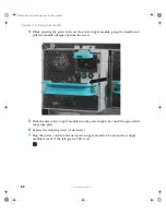
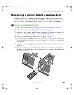
While pressing the green latch on the power supply module, grasp the handle and
pull the module straight out from the server.
5
Slide the new power supply module into the power supply bay until the green latch
snaps into place.
6
Replace the shipping screw (if necessary).
7
Plug the power cord into the new power supply module. The new power supply
module is ready if the left (green) LED is on.
8510725.book Page 82 Tuesday, May 17, 2005 5:45 PM
Summary of Contents for 9510
Page 1: ...Gateway 9510 Server User Guide ...
Page 187: ...182 www gateway com Appendix A 8510725 book Page 182 Tuesday May 17 2005 5 45 PM ...
Page 213: ...208 www gateway com Appendix C 8510725 book Page 208 Tuesday May 17 2005 5 45 PM ...
Page 221: ...216 www gateway com 8510725 book Page 216 Tuesday May 17 2005 5 45 PM ...
Page 222: ...A MAN 9510 USR GDE R1 04 05 ...


