144
www.gateway.com
Chapter 4: Installing Components
7
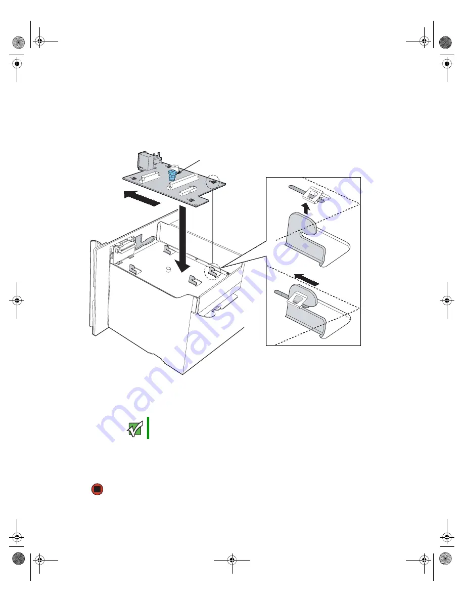
Remove the new front panel I/O board from its package and place it in the chassis,
engaging the mounting tabs on the chassis with the slots in the new board.
8
Slide the front panel I/O board forward until it is seated on the mounting tabs, then
tighten the blue, captive thumbscrew to secure the board. See
for correct tightening specifications.
9
Connect the front panel I/O board and control panel cables to the new front panel
I/O board.
10
Reinstall the processor air baffle by following the instructions in
installing the processor air baffle” on page 67
11
Follow the instructions in
“Closing the server case” on page 72
Important
Make sure that the pins on the front panel I/O board line up correctly
with the front panel cable connector.
Blue, captive thumbscrew
Mounting
tab
8510702.book Page 144 Thursday, July 7, 2005 11:21 AM
Summary of Contents for 9715
Page 249: ...244 www gateway com Appendix B 8510702 book Page 244 Thursday July 7 2005 11 21 AM ...
Page 259: ...254 www gateway com Appendix D 8510702 book Page 254 Thursday July 7 2005 11 21 AM ...
Page 277: ...272 www gateway com 8510702 book Page 272 Thursday July 7 2005 11 21 AM ...
Page 278: ...MAN 9715 SRV USR GDE R0 06 05 ...


