background image

BIOS Setup     63

Memory Reservation screen

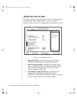
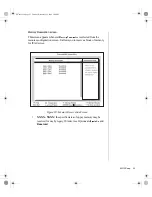
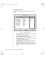
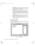
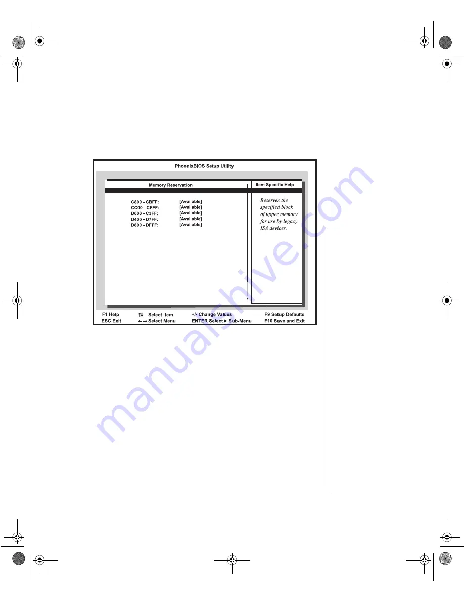
This screen appears whenever

Memory Reservation

is selected from the 

resource configuration screen. It allows you to reserve a block of memory 
for ISA devices.

Figure 30: Memory Reservation Screen

XXXX - XXXX: the specified area of upper memory may be 
reserved for use by legacy ISA devices. Options are

Available

and 

Reserved

.

4079tl.book  Page 63  Tuesday, December 22, 1998  2:04 PM

Summary of Contents for ALR 8200

Page 1: ...Maintaining and Troubleshooting the Gateway ALR 8200 Server Part 8504079 A MAN SYS US 8200 TECH REF R3 12 98 4079tl book Page 1 Tuesday December 22 1998 2 04 PM...

Page 2: ...e logo and Pentium are registered trademarks and MMX is a trademark of Intel Corporation Microsoft MS MS DOS and Windows are trademarks or registered trademarks of Microsoft Corporation All other prod...

Page 3: ...the wrap around panel 7 Reinstalling the side panel 8 Components 9 System board 10 Chassis fans 12 Power connectors 12 Front panel connectors 13 Drive controllers and connectors 14 Server management...

Page 4: ...tware 50 Installing video drivers 50 Installing the USB driver 50 Installing the NetWare 4 11 driver 51 BIOS Setup 53 About the BIOS Setup utility 54 Using the BIOS Setup utility 55 Main menu screen 5...

Page 5: ...ifications 100 Memory map 101 I O map 102 IRQ Usage 103 DMA Usage 104 Regulatory compliance statements 105 FCC Notice 105 Industry Canada Notice 105 CE Notice 106 VCCI Notice 106 Australia New Zealand...

Page 6: ...iv Maintaining and Troubleshooting the Gateway ALR 8200 Server 4079tl book Page iv Tuesday December 22 1998 2 04 PM...

Page 7: ...Preface About this guide vi Conventions used in this guide vii Important safety instructions viii 4079tl book Page v Tuesday December 22 1998 2 04 PM...

Page 8: ...ponents covers information on maintaining replacing and upgrading the components in the system This section includes information about options for the system and installation instructions Chapter 3 In...

Page 9: ...d simultaneously Setup Commands to be entered options to select and messages that appear on your monitor are printed in bold User s Guide Names of publications and files are printed in italic An impor...

Page 10: ...nsert the plug into the outlet contact your electrician to replace the outlet Do not walk on the power cord or allow anything to rest on it If you use an extension cord with this system make sure the...

Page 11: ...nto the system The system does not operate properly when the operating instructions are followed The system was dropped or the cabinet is damaged The product exhibits a distinct change in performance...

Page 12: ...x Maintaining and Troubleshooting the Gateway ALR 8200 Server 4079tl book Page x Tuesday December 22 1998 2 04 PM...

Page 13: ...1 System Access Static electricity precautions 2 Opening the system 3 Closing the system 6 4079tl book Page 1 Tuesday December 22 1998 2 04 PM...

Page 14: ...electrostatic damage to your system components Avoid static causing surfaces such as plastic and styrofoam in your work area Remove the parts from their antistatic bags only when you are ready to use...

Page 15: ...ssis keylock if necessary 2 On the rear of the system remove the two screws that secure the side panel to the chassis Save the screws 3 Slide the panel back and gently pull it off of the chassis see F...

Page 16: ...emove the two screws that secure the panel to the chassis Also remove the screw at the top of the system See Figure 2 Save the screws Figure 2 Removing the Wrap Around Panel 4 Slide the panel backward...

Page 17: ...age 3 and Removing the wrap around panel on page 4 3 Disconnect the two ribbon cables that link the bezel LED indicators to the interior of the system 4 Remove the six screws that secure the bezel to...

Page 18: ...t the bezel pegs are aligned with the mount holes on the front of the chassis See Figure 4 Figure 4 Reinstalling the Bezel 2 Carefully thread the ribbon cables through the openings in the chassis and...

Page 19: ...panel 1 Hold the wrap around panel at a slight angle over the chassis as shown in Figure 5 Figure 5 Reinstalling the Wrap Around Panel 2 Lower the panel and anchor its top edge to the chassis 3 Gently...

Page 20: ...e panel with the chassis ledges just a few inches off towards the back of the chassis See Figure 6 Figure 6 Reinstalling the Side Panel 2 Verify that the slots on the panel are aligned with the lockin...

Page 21: ...2 Components System board 10 The RAID backplane 21 4079tl book Page 9 Tuesday December 22 1998 2 04 PM...

Page 22: ...etween the processor memory and peripherals See the table below and on the following pages for the key to Figure 7 Figure 7 System Board Components A Chassis fan connector B Power connectors C Standby...

Page 23: ...itch connector T Speaker connector U External boot ROM connector V I2 C connector W SCSI B connector X SCSI A connector Y Clear CMOS jumper Z Battery AA ISA slot 2 AB ISA slot 1 shared with secondary...

Page 24: ...D cage connector BD LED display connector Chassis fans There are several chassis fan connectors on the system board These connectors provide power for cooling fans that may be positioned in several pa...

Page 25: ...s switch will not reset the processor or remove the fault condition it clears the fault alert flag and causes the fault LED to turn off If the fault condition persists the processor fault LED will tur...

Page 26: ...nt panel to the system board Includes the keyboard lock button signals and the reset button signals Drive controllers and connectors The system board supports several controllers for drives and other...

Page 27: ...mentation maximizing data transfer on PCI local bus at 133 MB sec data bursts SCAM SCSI Configured Automatically Level 1 for Windows 95 enabling automatic configuration of new devices without having t...

Page 28: ...SI backplane to the system board to allow status and monitoring of backplane fan activity The signals provide backplane fan tachometer readings Not implemented in this system System jumpers These jump...

Page 29: ...ight expansion slots five PCI slots one ISA slot one PCI RAIDport and one shared PCI ISA slot The PCI bus processes peripheral transactions at a system clock speed of up to 33 MHz I O connectors The I...

Page 30: ...daisy chained from each port Hot swap capability and dynamic resource allocation for all peripherals attached Data transfer rates of up to 12Mbps USB drivers are provided as a part of most major oper...

Page 31: ...nents as described in the following paragraphs CPUs and CPU slots Depending on the model the system is equipped with one Intel Pentium II processor with 512 KB ECC L2 cache integrated into a Single Ed...

Page 32: ...that adjusts the voltage supplied to the CPU The VRM for the first CPU CPU 1 is embedded on the system board Memory The system comes standard with 64 MB of Error Checking and Correcting ECC RAM System...

Page 33: ...al RAID subsystem is controlled by a RAID Caching Controller Hot swapping is a useful feature that allows you to replace a failed hard disk drive without interrupting system operation In the event of...

Page 34: ...22 Maintaining and Troubleshooting the Gateway ALR 8200 Server 4079tl book Page 22 Tuesday December 22 1998 2 04 PM...

Page 35: ...e processor 24 Installing a second processor 27 Setting system board jumpers 29 Installing memory 31 Adding and replacing drives 36 Installing and using drivers and other software 50 4079tl book Page...

Page 36: ...or overheats and fails if it is not cooled sufficiently The heat sink provided with the Pentium II processor on the system provides all necessary cooling for the processor 1 Turn off the system and di...

Page 37: ...he processor cartridge that you removed in a safe place 7 Remove the replacement processor cartridge from its protective wrapping and place it in the cartridge supports for the slot 1 connector 8 Slid...

Page 38: ...the lock bar on the top of the processor cartridge and replace the two screws that secure it in place 10 Set the jumpers properly for the new processor configuration 11 Close the case see page 6 for i...

Page 39: ...h Pentium II processor The Pentium II processor overheats and fails if it is not cooled sufficiently The heat sink provided with the Pentium II processor on the system provides all necessary cooling f...

Page 40: ...7 Set the jumpers correctly for the new processor configuration 8 Insert the new VRM into the connector provided until the release latches click into place 9 Close the case as described in chapter 1...

Page 41: ...ging jumper shunts on the block If you upgrade your processor you may need to change jumper settings The JP22 jumper configuration block lets you set the processor speed The system automatically detec...

Page 42: ...d 2 Open the case see page 3 for instructions observing the static electricity precautions on page 2 3 Move the jumper shunt on the JP15 jumper to connect pins 2 and 3 4 Wait a few seconds while the C...

Page 43: ...ion chart later in this section for valid memory configurations You may select any combination that provides the total RAM required by your system and applications 1 Turn off the system and disconnect...

Page 44: ...press the DIMM into the socket until it doesn t move any farther Inserting the DIMM automatically locks each of the socket clamps on each end of the DIMM 6 Close the case see page 6 for instructions 7...

Page 45: ...om the socket Figure 15 Opening the DIMM Socket Clamps 2 Carefully lift the DIMM out of the socket Figure 16 Removing the DIMM 3 Store the DIMM in a static free container To remove DIMMs Caution Never...

Page 46: ...2x72 16 2x72 16 2x72 16 2x72 16 64 4x72 32 4x72 32 64 4x72 32 2x72 16 2x72 16 64 8x72 64 96 8x72 64 4x72 32 96 8x72 64 2x72 16 2x72 16 96 4x72 32 4x72 32 2x72 16 2x72 16 128 16x72 128 128 8x72 64 8x72...

Page 47: ...256 512 32x72 256 16x72 128 16x72 128 512 32x72 256 16x72 128 8x72 64 8x72 64 512 16x72 128 16x72 128 16x72 128 16x72 128 1 GB 32x72 256 32x72 256 32x72 256 32x72 256 Total MB DIMM Socket 1 DIMM Socke...

Page 48: ...orientation You will reconnect these cables after you install the new drive 4 Remove the screws securing the drive bracket to the system chassis and remove the drive from the chassis 5 Remove the cre...

Page 49: ...4 Disconnect the power and data cables from the back of the drive noting their location and orientation You will reconnect these cables after you install the new CD ROM drive 5 Remove the screws secur...

Page 50: ...removed in Step 5 11 Connect the power and data cables to the CD ROM drive making sure the cables match their original position See drive documentation for proper drive jumper settings and cable orie...

Page 51: ...front bezel If you are replacing an existing drive disconnect the power and data cables from the drive noting their location and orientation You will reconnect these cables after you install the new d...

Page 52: ...s you removed in Step 5 11 Connect the power and data cables to the back of the drive See drive documentation for proper drive jumper settings and cable orientation 12 Close the case see page 6 for in...

Page 53: ...structions observing the static electricity precautions on page 2 3 Disconnect the data and power cables from the drive in the top drive bay 4 Remove the two screws that secure the right side of the d...

Page 54: ...ng the two screws you just removed see Figure 20 Figure 20 Replacing the 3 5 Inch Drive in the Top Drive Bay 7 Place the new drive and bracket in the top drive bay and secure them with the four screws...

Page 55: ...inch drive bay at the back of the chassis The RAID bay supports up to six 3 5 inch LVD SCA SCSI hard drives 1 Unlock and open the lower bezel door 2 Locate the SCA hard disk that you want to replace...

Page 56: ...ve into the bay until the connector makes contact with the SCA connector on the backplane see Figure 22 Figure 22 Installing an SCA Drive 7 Press the drive in firmly until the connector seats securely...

Page 57: ...tricity precautions on page 2 4 Use a straight blade screwdriver to remove the punchout section on the rear panel of the chassis insert the blade of the screwdriver into the slot in the punchout then...

Page 58: ...a RAID port card Some ISA expansion cards have jumpers or switches that set interrupts and I O addresses They come with instructions that explain how to set them to avoid hardware conflicts Follow th...

Page 59: ...he card See the card documentation for proper jumper settings and cable orientation 9 Close the case see page 6 for instructions 10 Reconnect the power cord and turn on the system It may be necessary...

Page 60: ...e system board The battery is circular and has the positive pole mark on the top 6 Gently pull the battery from its socket and press the new battery in the socket with the positive pole up Be sure you...

Page 61: ...ies Turn off the system remove the cover and verify that all cables inside the case are attached securely Also make sure that the colored cable edges are aligned correctly and that the connectors didn...

Page 62: ...iver To use a USB device you must install the USB driver in a computer running Windows 95 A 3 5 inch diskette labeled Integrated Controller UATA files for Win 95 was shipped with your computer You mus...

Page 63: ...ver will generate interrupts that hang the server To resolve this issue replace the MPS14 PSM file that is installed during the NetWare 4 11 installation with an updated version of the file The update...

Page 64: ...52 Maintaining and Troubleshooting the Gateway ALR 8200 Server 4079tl book Page 52 Tuesday December 22 1998 2 04 PM...

Page 65: ...4 BIOS Setup About the BIOS Setup utility 54 Using the BIOS Setup utility 55 Updating the BIOS 74 4079tl book Page 53 Tuesday December 22 1998 2 04 PM...

Page 66: ...d to serve as a guide so that you can make changes to your system s BIOS when necessary Many of the screen examples that you will see in this chapter are identical to what you see on your monitor howe...

Page 67: ...u Back Press ESC to back out of any field Next and Previous Item Press the up arrow or down arrow keys to move to the next or previous menu item Select Menu Use the left arrow and right arrow keys to...

Page 68: ...ty four hour clock System Date lets you set the system date Legacy Diskette A allows you to select the type of diskette drive installed as drive A The options are 360 kB 5 1 2 MB 5 720 kB 3 1 44 1 25...

Page 69: ...n on page 58 Secondary Master opens the Secondary Master screen to permit you to setup the secondary master hard disk drive Details of this screen are provided in the section Hard Disk Drive Setup scr...

Page 70: ...a set of previously defined drive types and sizes These values only apply to older drives generally less than 200 MB in size User Selecting this option brings up a sub menu where you can enter the CY...

Page 71: ...es Logical Block Addressing to be used in place of Cylinders Heads and Sectors The options are ENABLED and DISABLED 32 Bit I O enabling this option allows 32 bit communication between the CPU and the...

Page 72: ...g system is compatible with Plug and Play The options are Yes and No Reset Configuration Data selecting Yes causes the system to clear its configuration data and automatically configure all PnP device...

Page 73: ...mory screen on page 68 Advanced Chipset Control opens the advanced chipset control screen which contains a single field The field isECC Config which allows you to set the extent of error checking and...

Page 74: ...ry Reservation screen This screen allows the user to reserve blocks of upper memory for use by legacy ISA devices Details of this screen are provided in the section Memory Reservation screen on page 6...

Page 75: ...he resource configuration screen It allows you to reserve a block of memory for ISA devices Figure 30 Memory Reservation Screen XXXX XXXX the specified area of upper memory may be reserved for use by...

Page 76: ...ver you select IRQ Reservation from the advanced menu screen It allows you to manually reserve IRQs for specific devices Figure 31 IRQ Reservation Screen IRQx the specified IRQ may be reserved for use...

Page 77: ...options include Enabled Disabled and Auto Base I O Address displays the base I O address for integrated Serial Port A Using the or key displays the optional addresses available Interrupt displays the...

Page 78: ...ions include ECP Extended Capabilities Port Bi directional and Output only Base I O Address displays the base I O address for the integrated Parallel Port Using the or key displays the optional addres...

Page 79: ...ptions areEnable andDisable Enable causes an audible click when each key is pressed Keyboard Auto Repeat Rate determines the rate at which a character repeats if a key is held down Options are 2 sec 6...

Page 80: ...em BIOS Area controls the caching of the system BIOS area Options are Uncached or Write Protect Cache Video BIOS Area controls the caching of the video BIOS area Options are UNCACHED or Write Protect...

Page 81: ...led Security menu screen This screen allows you to set system security characteristics Figure 35 Security Menu Screen Supervisor Password displays status of administrative password Options are Clear n...

Page 82: ...fy the password used to control access to the system at boot If the user password has already been set you must enter the current password before you are able to enter and verify the new password Pass...

Page 83: ...evice that the system polls second upon boot up Options include Diskette Drive Hard Drive Removable Devices ATAPI CD ROM Drive andNetwork Boot Third Boot Device designates the device that the system p...

Page 84: ...the next drive listed until an operating system is found Use the up and down arrows to select a device then press or to move it up or down the list Removable Devices displays a list of available remov...

Page 85: ...settings Load Setup Defaults displays the setup defaults in cases where the settings have been corrupted or incorrectly modified Press F1 to resume the boot or F2 to run the BIOS Setup with the ROM de...

Page 86: ...website 5 Uncompress the contents of the BIOS file you downloaded and copy the contents onto a bootable diskette 6 Place the bootable diskette containing the BIOS files into drive A then restart the s...

Page 87: ...ck to defaults using the F5 key or the correct values from your earlier configuration the system may function erratically You may encounter a CMOS checksum error or other problem after the system rest...

Page 88: ...76 Maintaining and Troubleshooting the Gateway ALR 8200 Server 4079tl book Page 76 Tuesday December 22 1998 2 04 PM...

Page 89: ...ROM problems 80 Hard disk problems 82 Memory processor problems 83 Modem problems 84 AC power problems 85 Peripheral adapter problems 86 Printer problems 88 System problems 89 Video problems 91 Error...

Page 90: ...procedure correctly and completely If an error occurs in an application consult the documentation supplied with the software This section identifies solutions to common problems If the suggestions in...

Page 91: ...he system cover while the system is turned on Do not attempt to open the monitor it is extremely dangerous Even if the monitor s power is disconnected stored energy in the monitor s components can cau...

Page 92: ...a and then click Volume Control Make certain the volume is turned up The sound card may not be installed correctly Some systems do not have sound cards because sound capabilities are built into the sy...

Page 93: ...Support The secondary IDE device may be disabled Restart your computer and then press F1 to enter the setup program From the Peripheral Configuration Advanced menu set the Secondary IDE Interface to A...

Page 94: ...address Change the device s SCSI address to one that is not currently being used by the system The cables are not connected correctly Open the system and check the cable connections Probable Cause So...

Page 95: ...which chip or memory segment is failing Probable Cause Solution The processor was installed incorrectly or in the wrong socket Check the installation The processor should be recognized automatically...

Page 96: ...d plugged into the appropriate port on the modem line port The modem is not configured with a valid interrupt or address Check the system settings for conflicts If one exists correct the problem by se...

Page 97: ...matically powers on when AC cord is plugged in Probable Cause Solution A power outage or shortage may have corrupted the CMOS chip Re configure the BIOS If problem persist call Technical Support 4079t...

Page 98: ...to the device The SCSI chain is not terminated Make certain the last device on the SCSI chain is terminated The device cables are not installed correctly Open the system and check all cables between...

Page 99: ...protected Probable Cause Solution The diskette is corrupted Remove the diskette from the drive If the light remains on try restarting the system The cable to the drive is not connected properly Open t...

Page 100: ...er and the system Make certain it is connected to the proper port Check the connector and cable for bent or broken pins The printer is not designated as the default printer If the printer to which you...

Page 101: ...C IN connectors on rear of computer Verify that both power supplies are set to the correct voltage range 115 V AC or 230 V AC Verify that both power supplies are turned on Replace defective power supp...

Page 102: ...ot plugged in or connected properly Check the cable Make certain it is plugged in correctly The mouse driver did not load when the system booted Load the appropriate mouse driver manually or contact T...

Page 103: ...or damaged pins The monitor is defective Connect a working monitor to the computer The monitor brightness and contrast controls are turned down Adjust the brightness and contrast knobs to the center...

Page 104: ...itor Make certain the monitor is turned on and then restart the system The display type is set incorrectly From the Control Panel window Start Settings Control Panel double click Display set the displ...

Page 105: ...protector or UPS is damaged Disconnect the monitor power cable and connect it directly to the power source The monitor is too close to a source of electrical interference Move the monitor away from so...

Page 106: ...o exit MS DOS to return to Windows type exit and press ENTER Base memory xxx expansion This is an informational message only No action is required Checking RAM on disk controller Your BIOS configurati...

Page 107: ...T Hard disk controller failure Make certain the hard disk cable is properly connected Open the BIOS Setup program and verify that the correct drive type is selected Hard disk controller failure press...

Page 108: ...working keyboard Make certain the keyboard is compatible with the system You may have to change the switch setting to AT Replace the keyboard chip Keyboard controller failure Try a working keyboard Ma...

Page 109: ...ht command If you are trying to exit MS DOS to return to Windows type exit and press ENTER Syntax error Make certain you entered the right command If you are trying to exit MS DOS to return to Windows...

Page 110: ...98 Maintaining and Troubleshooting the Gateway ALR 8200 Server 4079tl book Page 98 Tuesday December 22 1998 2 04 PM...

Page 111: ...A Appendix Specifications 100 Memory map 101 I O map 102 IRQ Usage 103 DMA Usage 104 Regulatory compliance statements 105 4079tl book Page 99 Tuesday December 22 1998 2 04 PM...

Page 112: ...ernet onboard SCSI controller and a full complement of I O ports Dimensions 24 5 H x 7 75 W x 27 0 D 65 lbs Processor Pentium II Processor speed 266 300 333 350 400 or 450 MHz Processor upgrade Slot 1...

Page 113: ...rs 896 KB 1024 KB 1 MB 000E 0000 000F FFFF 128 KB System BIOS ROM Above 1 MB 1 MB 16 MB 0010 0000 00FF FFFF 15 MB Extended Memory 15 MB 16 MB 00FE 0000 00FF FFFF 64 KB Mapped RAM or ROM Above 16 MB 16...

Page 114: ...te Programmable interval timer 2 0049 1 byte Reserved 004A 1 byte CPU speed control counter 2 004B 1 byte Command mode register 0061 0070 16 bytes NMI status registers 0080 008F 16 bytes DMA page regi...

Page 115: ...esource NMI 0 System Timer 1 Keyboard 2 Cascade 3 Serial port 2 COM2 4 Serial port 1 COM1 5 Secondary Parallel Port LPT2 6 Floppy Controller 7 Primary Parallel Port LPT1 8 Real Time Clock RTC 9 Cascad...

Page 116: ...the direct memory access DMA channels that the system typically uses and which ones are available for use by add in devices DMA Resource 0 Cascade 1 Available 2 Floppy Controller 3 Available 4 Redirec...

Page 117: ...n outlet on a circuit different from that to which the receiver is connected Consult the dealer or an experienced radio TV technician for help This equipment has been tested and found to comply with t...

Page 118: ...000 3 3 1995 EN50082 1 1992 according to EN 61000 4 2 1995 or IEC 801 2 1984 ENV 50140 1994 or IEC 801 3 1984 EN 61000 4 4 1988 or IEC 801 4 1998 ii Low Voltage Directive Safety 73 23 EEC as per EN 60...

Page 119: ...comply with the limits for a Class A digital device pursuant to the Australian New Zealand standard AS NZS 3548 set out by the Spectrum Management Agency Caution Disconnect power before servicing Aust...

Page 120: ...108 Maintaining and Troubleshooting the Gateway ALR 8200 Server 4079tl book Page 108 Tuesday December 22 1998 2 04 PM...

Page 121: ...I O Address field Serial Port B 66 boot disk write protection 70 Boot menu screen 71 C800 CBFF field 63 Cache Base 0 512K field 68 Cache Base 512K 640K field 68 Cache C800 CBFF field 69 Cache CC00 CFF...

Page 122: ...field 61 LBA Mode Control field 59 Legacy Diskette A field 56 Legacy Diskette B field 56 Load Setup Defaults field 73 Main menu screen 56 Maximum Capacity field 58 Memory Cache field 68 Memory Reserva...

Page 123: ...he D400 D7FF Setup utility field 69 Cache D800 DBFF Setup utility field 69 Cache DC00 DFFF Setup utility field 69 Cache Extended Memory Area Setup utility field 69 Cache Memory Setup screen 68 Setup u...

Page 124: ...ventions vii drives hot swap 21 RAID controller 21 supported number 21 supported sizes 21 E Embedded PCI NIC Setup utility field 61 Embedded PCI SCSI Channel A Setup utility field 61 Channel B Setup u...

Page 125: ...ort B Setup utility field 66 IRQ Reservation Setup screen 64 Setup utility field 62 IRQ usage 103 IRQx Setup utility field 64 ISA expansion slots 17 J jumpers clear CMOS 30 processor bus speed 29 sett...

Page 126: ...4 SCSI controller 15 PCI ISA expansion slot 17 PCI RAIDport expansion slot 17 Peripheral Configuration Setup screen 65 Setup utility field 61 peripheral devices troubleshooting 86 Plug and Play O S Se...

Page 127: ...ndary Slave Setup utility field 57 Sectors Setup utility field 58 security supervisor password 70 user password 70 Security menu Setup screen 69 Serial Port A Setup utility field 65 Serial Port B Setu...

Page 128: ...ive field 72 Heads field 58 Interrupt field Parallel Port 66 Interrupt field Serial Port A 65 Interrupt field Serial Port B 66 IRQ Reservation field 62 IRQ Reservation screen 64 IRQ10 field 64 IRQ11fi...

Page 129: ...ld 59 Type field 58 Ultra DMA Mode field 59 updating the BIOS 74 Use Multiprocessor Specification field 60 User Password field 69 using 55 SHM Address Setup utility field 61 side panel removing 3 repl...

Page 130: ...ity field 58 U Ultra DMA Mode Setup utility field 59 UltraDMA controller 14 UltraSCSI controller 15 updating BIOS 74 USB driver installing 50 Use Multiprocessor Specification Setup utility field 60 Us...

Reviews: