38 Maintaining and Troubleshooting the Gateway ALR 9200 Server
8.
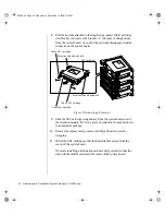
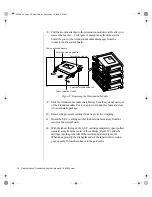
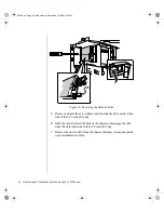
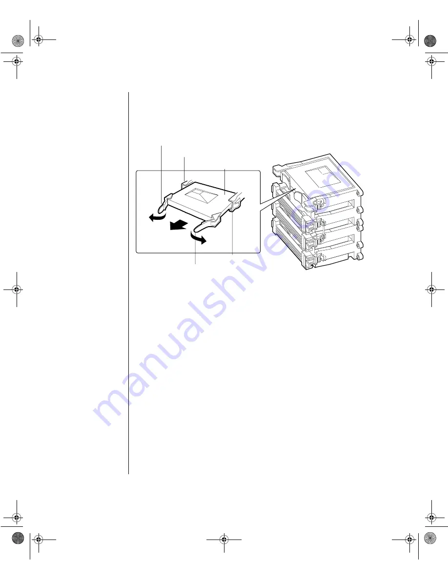
Pull the two tabs attached to the termination module (visible after you
remove the bracket—C in Figure 9) straight away from the system
board. As you do, the termination module disengages from the
connector on the system board.
Figure 9: Removing the Termination Module
9.
Slide the termination module straight away from the system board, out
of the retention module. Put it on a piece of conductive foam and store
it in an antistatic package.
10.
Remove the processor cartridge from its protective wrapping.
11.
Orient the S.E.C. cartridge so that the heat sink faces away from the
center of the system board.
12.
With the tabs at the top of the S.E.C. cartridge completely open (pulled
outward, away from the center of the cartridge, Figure 10), slide the
cartridge into the guide rails of the retention module (Figure 10).
When done properly, the triangular ends of the tabs (with two round
pegs on each) fit into the entrance to the guide rails.
Tab on retention module
Tab on retention module
Retention module guide rail
Retention module guide rail
Termination module
3424.boo Page 38 Wednesday, September 2, 1998 9:23 AM

