146
Chapter 6
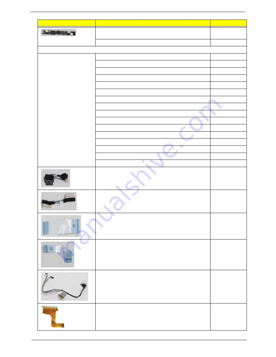
Suyin Camera Rosa 2G, MODULE CN0316-S30C-
OV06-1
57.S6507.001
CAMERA CNF9011(CMOS,0.3M,VGA)
57.S6507.002
CABLE
POWER CORD US 3PIN ROHS
27.TAXV7.001
POWER CORD(EU) 1.8M 3PBLACK FM010008-010
27.TATV7.001
POWER CORD AU W/LABEL (3 PIN)
27.A50V7.003
POWER CORD PRC 3P Y536B30001218008
27.TATV7.004
POWER CORD UK 3PIN
27.A03V7.004
POWER CORD US-110V (BSMI)
27.A99V7.002
POWER CORD SWISS 3 PIN
27.A99V7.004
PWR CORD(ISR)1.8M 3PBLK FZ0I0008-038
27.TATV7.005
POWER CORD ITALIAN 3PIN
27.A99V7.005
POWER CORD(S.A) 1.8M 3BLACK FZ010008-006
27.T48V7.001
PWR CORD V943B30001218008 DANISH 3P
27.A03V7.006
PWR CORD V943B30001218008 DANISH 3P
27.A03V7.006
POWER CORD AF-S (INDIA)
27.A50V7.001
POWER CORD ARGENTINE 3 PIN BLACK
27.S0207.001
POWER CORD JAPANESE
27.TAXV7.003
POWER CORD BRAZIL IMETRO 3 PIN
27.S0607.001
BLUETOOTH CABLE
50.SA107.001
CRT CABLE
50.SA107.002
FFC CABLE - CARD READER/B TO MB
50.SA107.003
FFC CABLE - LED/B TO MB
50.SA107.004
LCD CABLE W/MIC FOR CCD
50.SA107.005
FPC CABLE - HDD TO MB
50.SA107.006
CATEGORY
PARTNAME
ACER P/N.
Summary of Contents for EC14
Page 6: ...VI ...
Page 10: ...X Table of Contents ...
Page 34: ...24 Chapter 1 ...
Page 50: ...40 Chapter 2 ...
Page 60: ...50 Chapter 3 5 Pull the memory module out ...
Page 71: ...Chapter 3 61 8 Lift up and pull the button board to main board FCC free ...
Page 89: ...Chapter 3 79 4 Lift the LCD panel out lifting the bottom of the panel first ...
Page 93: ...Chapter 3 83 5 Remove the antennas completely ...
Page 99: ...Chapter 3 89 3 Apply adhesive and stick the microphone down ...
Page 108: ...98 Chapter 3 3 Connect the speaker connector ...
Page 116: ...106 Chapter 3 5 Relay the WLAN cables around and through the lower case ...
Page 127: ...Chapter 3 117 4 Place the HDD cover in from one edge 5 Tighten the four captive screws ...
Page 130: ...120 Chapter 3 ...
Page 170: ...160 ...


