16
Chapter 1
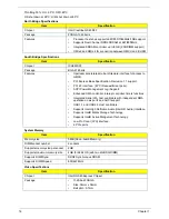
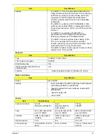
Throttling 50%: On= 90°C; OFF=80°C
OS shut down at 95°C; H/W shut down at 85°C
North Bridge Specifications
South Bridge Specifications
System Memory
Video Specifications
Item
Specification
Chipset
Intel Crestline GS45 SFF
Package
FCBGA 1363 balls
Features
•
Processor hosts bus supports 667/800/1066MHz FSB support.
•
Supports Dual Channel DDR2 SDRAM at 667/800MHz
•
Integrated SDRAM controller up to 8GB (2 SODIMM support)
•
DMI x2 and DMI x4 for connection between GMCH and ICH9M
Item
Specification
Chipset
ICH9M SFF
Package
BGA 676 balls
Features
•
Upstream accelerated Hub architecture interface for access to
GMCH.
•
PCI Express Base Specification, Revivsion 1.1 support.
•
PCI 2.3 interface. (4 PCI Request/Grant pairs).
•
ACPI Power Management Logi Support.
•
Enhanced DMA controller, interupt controller, timers functions.
•
Integrated Serial ATA host controllers with independent DMA
operation on six ports and AHCI support.
•
USB 1.1 and USB 2.0 Host controllers.
•
Supports Intel High Definition Audio (Intel HD Audio) Interface.
•
Supports Intel® Matrix Storage Technology.
•
Supports Intel® Active Mangement Technology.
•
Low Pin Count (LPC) interface.
•
6 PCle ports.
Item
Specification
Memory size
0MB (No on-board Memory)
DIMM socket number
2 sockets
Supports memory size per socket
2GB
Supports maximum memory size
4GB for 64bit OS (with two 2GB SO-DIMM)
Supports DIMM type
DDR2 Synchronous DRAM
Supports DIMM Speed
800/667 MHz
Item
Specification
Chipset
Intel® GS45 Express Chipset
Package
•
1329-ball FCBGA
•
Size: 34mm x 34mm
•
Ball pitch: 0.7mm
Summary of Contents for EC14
Page 6: ...VI ...
Page 10: ...X Table of Contents ...
Page 34: ...24 Chapter 1 ...
Page 50: ...40 Chapter 2 ...
Page 60: ...50 Chapter 3 5 Pull the memory module out ...
Page 71: ...Chapter 3 61 8 Lift up and pull the button board to main board FCC free ...
Page 89: ...Chapter 3 79 4 Lift the LCD panel out lifting the bottom of the panel first ...
Page 93: ...Chapter 3 83 5 Remove the antennas completely ...
Page 99: ...Chapter 3 89 3 Apply adhesive and stick the microphone down ...
Page 108: ...98 Chapter 3 3 Connect the speaker connector ...
Page 116: ...106 Chapter 3 5 Relay the WLAN cables around and through the lower case ...
Page 127: ...Chapter 3 117 4 Place the HDD cover in from one edge 5 Tighten the four captive screws ...
Page 130: ...120 Chapter 3 ...
Page 170: ...160 ...


