Chapter 6
181
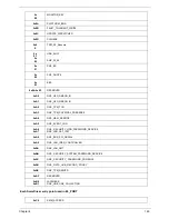
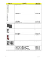
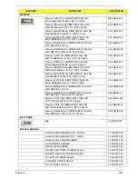
UPPER CASE ASSY BLACK W/TP , FFC*2
60.WGV07.001
LOWER CASE ASSY W/SPEAKER FOR 3G
60.WGV07.002
LOWER CASE ASSY W/SPEAKER FOR WIFI
60.WGV07.003
LCD BEZEL ASSY BLACK FOR GW
60.WGV07.004
LCD COVER ASSY GW BLACK W/ANTENNA
60.WGV07.005
UPPER CASE ASSY RED W/TP , FFC*2
60.WHJ07.001
LCD COVER ASSY GW RED W/ANTENNA
60.WHJ07.002
LCD COVER ASSY GW BLACK W/3G ANTENNA
60.WHN07.001
LCD COVER ASSY GW RED W/3G ANTENNA
60.WHP07.001
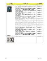
Camera
CAMERA MODULE
57.PND07.001
CATEGORY
PARTNAME
ACERPARTNO.
Summary of Contents for EC14T Series
Page 6: ...vi ...
Page 10: ...x Table of Contents ...
Page 13: ...Chapter 1 3 System Block Diagram ...
Page 32: ...22 Chapter 1 ...
Page 48: ...38 Chapter 2 ...
Page 65: ...Chapter 3 55 4 Unlock the FPC 5 Remove the FPC and keyboard ...
Page 67: ...Chapter 3 57 4 Partially open the LCD module 5 Remove the hinge cap ...
Page 83: ...Chapter 3 73 6 Remove the CRT cable ...
Page 96: ...86 Chapter 3 7 Pry up the bezel bottom edge 8 Remove the bezel ...
Page 106: ...96 Chapter 3 4 Remove the hinge ...
Page 110: ...100 Chapter 3 11 Remove both antenna cables from the cover ...
Page 124: ...114 Chapter 3 6 Replace the screw covers 7 Insert the stylus ...
Page 153: ...Chapter 3 143 2 Replace the HDD in the bay 3 Adhere the black tape 4 Replace the HDD FPC ...
Page 158: ...148 Chapter 3 ...
Page 206: ...196 Appendix B ...
Page 208: ...198 ...
Page 211: ...201 ...
Page 212: ...202 ...


