CHAPTER 3: Replacing notebook components
86
5
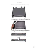
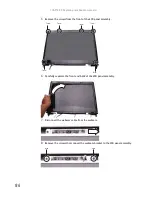
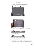
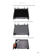
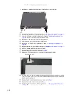
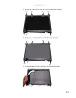
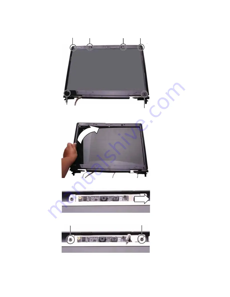
Remove the screws from the front of the LCD panel assembly.
6
Carefully separate the front and back of the LCD panel assembly.
7
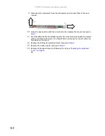
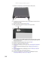
Disconnect the webcam cable from the webcam.
8
Remove the screws that connect the webcam bracket to the LCD panel assembly.
Screw
Screw
Screw
Screw
Screw
Screw
Screw
Screw
Summary of Contents for MG1
Page 1: ... MG1 SERVICEGUIDE ...
Page 11: ...5 System block diagram ...
Page 42: ...CHAPTER 1 System specifications 36 ...
Page 43: ...CHAPTER2 37 System utilities BIOS Setup Utility BIOS flash utility Removing a password lock ...
Page 56: ...CHAPTER 2 System utilities 50 ...
Page 167: ...CHAPTER5 161 Connector locations System board top connectors System board bottom connectors ...
Page 169: ...CHAPTER6 163 FRU Field Replaceable Unit list Introduction Exploded diagram FRU list ...
Page 178: ...CHAPTER 6 FRU Field Replaceable Unit list 172 ...
Page 185: ...APPENDIXC 179 Online support information ...
Page 190: ...Index 184 ...
Page 191: ......
Page 192: ...MAN GODZILLA SVC GDE R1 07 08 ...

