Chapter 3
83
LCD Module Disassembly Process
IMPORTANT:
Cable paths and positioning may not represent the actual model. During the removal and
replacement of components, ensure all available cable channels and clips are used and that the
cables are replaced in the same position.
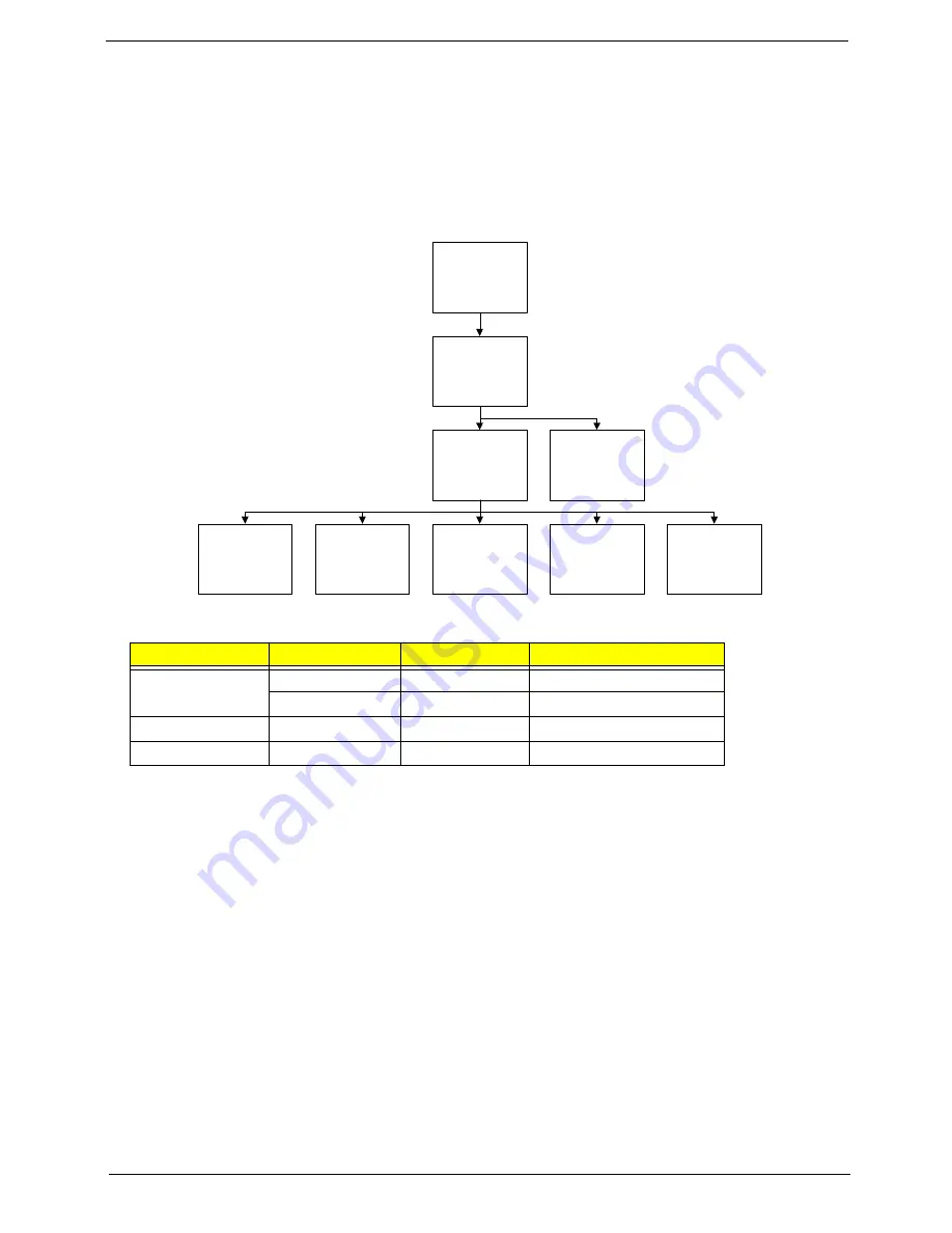
LCD Module Disassembly Flowchart
Screw List
Step
Screw
Quantity
Part No.
LCD Bezel
M2.5*6.0
6
86.W0907.002
M2*3
2
86.A08V7.005
LCD Panel
M2*3.5
4
86.T23V7.005
LCD Brackets
M2*3
4
86.A08V7.005
Re
m
ove
LCD Panel
Re
m
ove
LCD Bezel
Re
m
ove
LCD FPC Cable
Re
m
ove LCD
P
a
nel
f
ro
m
M
a
in
Unit be
f
ore
proceeding
Re
m
ove
LCD Brackets
Re
m
ove
Antennas
Re
m
ove
Camera Module
Re
m
ove
Microphone
Re
m
ove
Power Board
Summary of Contents for NV42 Series
Page 6: ...VI ...
Page 10: ...X Table of Contents ...
Page 34: ...24 Chapter 1 ...
Page 51: ...Chapter 2 41 ...
Page 52: ...42 Chapter 2 ...
Page 76: ...66 Chapter 3 7 Lift the Upper Cover clear of the computer as shown ...
Page 78: ...68 Chapter 3 ...
Page 80: ...70 Chapter 3 7 Lift the Speaker Modules clear of the Upper Cover ...
Page 85: ...Chapter 3 75 5 Disconnect the Bluetooth cable from the module ...
Page 87: ...Chapter 3 77 4 Turn the USB Board over and disconnect the USB cable from the board ...
Page 98: ...88 Chapter 3 4 Remove the LCD Panel rear edge first Place it on a clean surface ...
Page 144: ...134 Chapter 3 ...
Page 175: ...Chapter 6 165 ...
Page 178: ...Appendix A 168 ...
Page 196: ...186 Appendix C ...
Page 200: ...190 ...


