www.gateway.com
67
15
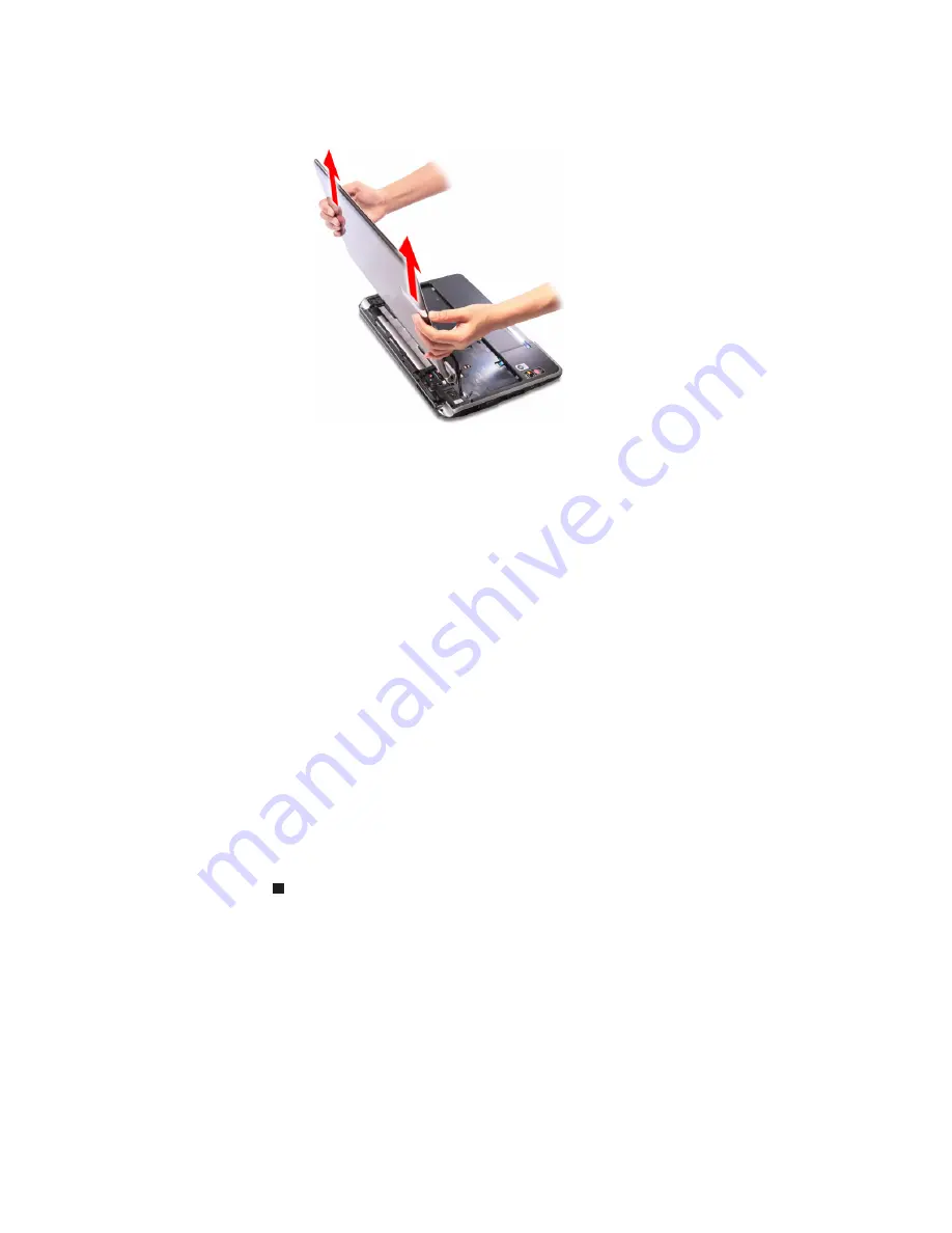
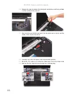
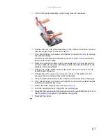
Lift the LCD panel assembly up and away from the notebook.
16
Position the new LCD panel assembly on the notebook, and then secure it
with the hinge screws removed in
step 14
.
17
If the notebook has a wireless card installed, proceed to
step 18
to arrange
the antenna cables.
If there’s no wireless card installed, proceed to
step 19
to reconnect the
power button board cable.
18
Refer to the antenna cable routing note made on
step 9
and secure the
antenna cables to the palm rest before pulling the ends downward to the
wireless card compartment.
19
Arrange the power button cable on the palm rest and reconnect it to its
system board connector.
20
Arrange the
LCD, webcam, and microphone cables
on the palm rest and
reconnect them to their system board connectors.
21
Close the LCD panel and turn the notebook over so the base is facing up.
22
If the notebook has a wireless card installed, reconnect the antenna cables
and then reinstall the bay cover.
23
Return the base hinge screws removed in
step 5
.
24
Turn the notebook over so the palm rest is facing up.
25
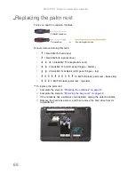
Reinstall the keyboard and the keyboard cover by performing steps
5
–
8
of
the
“Replacing the keyboard”
procedure on
page 62
.
26
Reinstall the battery.
Summary of Contents for NV55
Page 1: ... NV55 SERVICEGUIDE ...
Page 6: ...Contents iv ...
Page 12: ...CHAPTER 1 System specifications 6 System block diagram ...
Page 48: ...CHAPTER 2 System utilities 42 ...
Page 140: ...CHAPTER 4 Troubleshooting 134 ...
Page 141: ...CHAPTER5 135 Connector locations System board layout ...
Page 145: ...CHAPTER6 139 FRU Field Replaceable Unit list Introduction Exploded diagram FRU list ...
Page 152: ...CHAPTER 6 FRU Field Replaceable Unit list 146 ...
Page 153: ...APPENDIXA 147 Test compatible components Introduction Microsoft Windows 7 Compatibility Test ...
Page 156: ...APPENDIX A Test compatible components 150 ...
Page 157: ...APPENDIXB 151 Online support information ...
Page 163: ......
Page 164: ...MAN NV5x SVC GDE R1 04 09 ...


