CHAPTER 3: Replacing notebook components
90
5
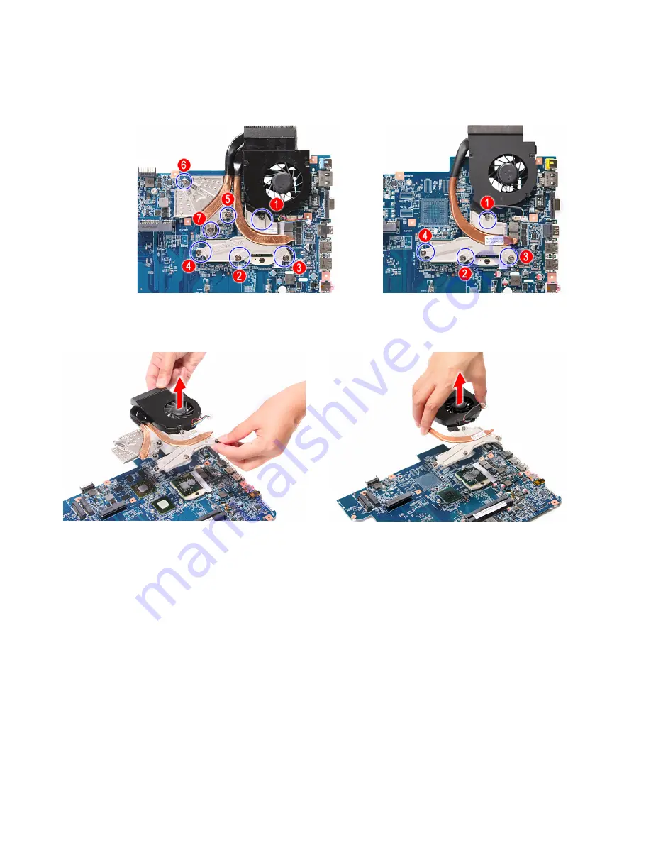
Loosen the spring-loaded captive screws securing the cooling assembly.
Follow the screw sequence indicated on the below images.
6
Remove the cooling assembly from the system board.
7
Lay the cooling assembly down in an upright position to avoid tainting your
work space with thermal grease.
Discrete model
UMA model
Discrete model
UMA model
Summary of Contents for NV55
Page 1: ... NV55 SERVICEGUIDE ...
Page 6: ...Contents iv ...
Page 12: ...CHAPTER 1 System specifications 6 System block diagram ...
Page 48: ...CHAPTER 2 System utilities 42 ...
Page 140: ...CHAPTER 4 Troubleshooting 134 ...
Page 141: ...CHAPTER5 135 Connector locations System board layout ...
Page 145: ...CHAPTER6 139 FRU Field Replaceable Unit list Introduction Exploded diagram FRU list ...
Page 152: ...CHAPTER 6 FRU Field Replaceable Unit list 146 ...
Page 153: ...APPENDIXA 147 Test compatible components Introduction Microsoft Windows 7 Compatibility Test ...
Page 156: ...APPENDIX A Test compatible components 150 ...
Page 157: ...APPENDIXB 151 Online support information ...
Page 163: ......
Page 164: ...MAN NV5x SVC GDE R1 04 09 ...


