Venice Single Board Computer Operating Manual
2. CONNECTORS
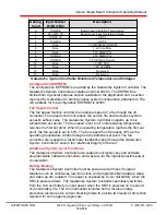
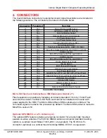
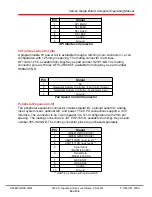
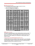
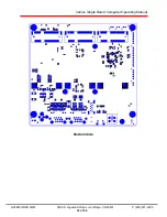
The board interface connector pin assignments and signal descriptions are included in
the following sections. The connectors are listed in the table below.
Connector Populated
Function
J1
Yes
Micro SD / Nano SIM Socket
J2
No
GPS Receiver MMCX Antenna
J3
Yes
Coin Cell Battery Socket
J4
No
Optional External Coin Cell Header
J5
No
5V Power Supply Input
J6
Yes
3.3V Power Supply Input
J7
Yes
Serial Peripheral Interface (SPI)
J8
No
5V Fan Speed Control
J9
Yes
Peripheral Expansion (GPIO, UART, I2C, ADC)
J10
Yes
Mini-PCIe Socket with PCIe and USB 2.0 and SIM
J11
Yes
SOM Connector
J12
Yes
Mini-PCIe Socket with PCIe and USB 2.0
J13
Yes
SOM Connector
J14
Yes
Mini-PCIe Socket with PCIe and USB 2.0
J15
Yes
RS232/RS485 Serial Ports
J16
Yes
Tamper Switch
J17
Yes
MIPI CSI and DSI Header
J18
No
Optional Power Input Header
J19
Yes
Input Power Barrel Jack
J20
Yes
Gigabit Ethernet Port and 802.3af PoE Input Power
J21
Yes
Gigabit Ethernet Port and Passive PoE Input Power
J22
Yes
USB Host Type A Socket
J23
No
Optional USB Header
J24
Yes
USB OTG Micro B Socket
J25
Yes
Test Header
J26
No
Optional Push Button Switch Header
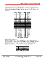
Connector Summary
Micro-SD Flash and Cellular Nano SIM Expansion Socket (J1)
Flash expansion is possible by installing an industry standard 11mm by 15mm Flash
card into the socket. The Micro-SD Flash card cannot be installed or removed with
power applied to the SBC. The Micro-SD and Nano SIM sockets are combined. The
command signal is routed to the processor.by default. The Nano SIM socket is routed to
Mini-PCIe socket J10.
Optional GPS MMCX or u.FL Antenna (J2)
The optional GPS feature includes an antenna connector for an externally mounted
passive or active antenna. The 50 Ohm MMCX antenna connector (standard loading
option) is a vertical mount Molex 73415-2061, or equivalent. The 50 Ohm U.FL
connector (optional) is a vertical mount Sunridge MCBG-ST-00T, or equivalent.
GATEWORKS.COM 3026 S. Higuera St San Luis Obispo, CA 93401
P:(805)781-2000
18 of 34

