background image

Instructions for PY300DCL

www.gatexpertstore.com

12

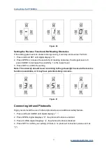
Figure 15

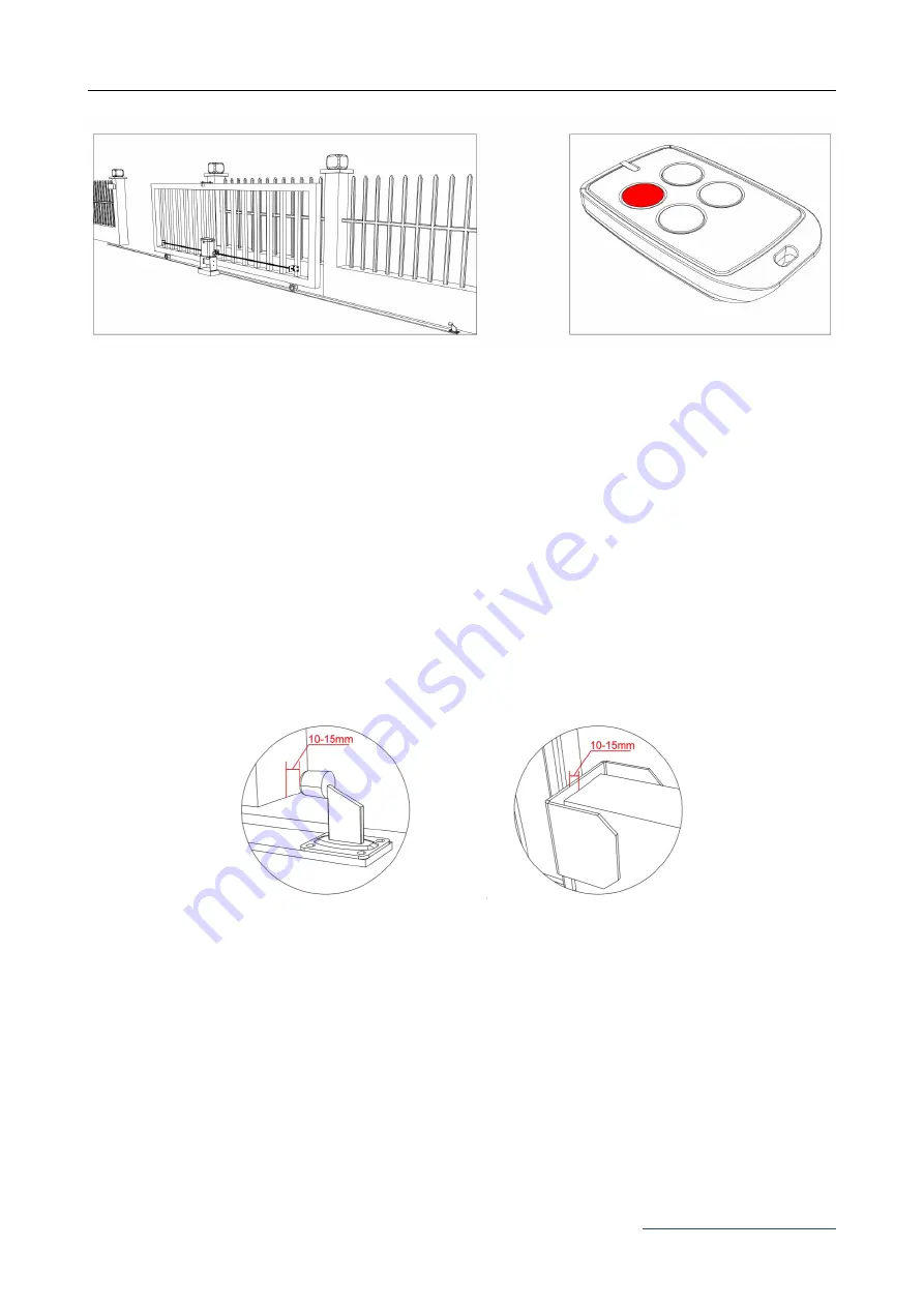
Step 8 - Testing Travel and Limit Stops

·

Ensure gate opener is installed as per step 5, 6 and the sliding gate is in the middle position.

·

Please refer to control board setting(page 15) to set the open limit stop position and closed limit
stop position. The ideal closed final position for the gate frame is 10-15mm from closed gate
end catch.

·

After setting up the limit stop positions, the sliding gate will automatically run to open limit stop
positon and then to the closed limit stop postion, do not cut off the power supply or stop the
gate during it’s Auto-running.

·

Press remote (remotes included in kit are factory paired to the motor) or exteral push button,the

sliding gate will begin to move. When it arriaves at the limit stop position the sliding gate will

stop.

Now the basic open and closed positions are set, for further setting functions and adjusting
parameters, please refer to pages 13-21 in this manual.

Open Limit Stop Position

Closed Limit Stop Position

Summary of Contents for PY300DCL

Page 1: ...Sliding Gate Opener User Manual PY300DCL Website www gatexpertstore com E mail sales gatexpertstore com...

Page 2: ...eration When mounting and positioning this product please ensure the power cable is unplugged The motor cover will need to be removed to mount the motor to the mounting plate or directly to the concre...

Page 3: ...eplace for free 4 The malfunction and damages caused by incorrect use or man fault is not covered by this warranty CONTACT US E mail sales gatexpertstore com Please fill in the order information in th...

Page 4: ...ng Installing Motor Cover 7 Step 4 Motor Pad Footing 8 Step 5 Fitting Mounting Base and Motor 8 Step 6 Sprocket and Chain Motor Alignment 10 Step 7 Powering on 11 Step 8 Testing Travel and Limit Stops...

Page 5: ...he opposite direction This will give you an understanding of the way how the opener moves the gate Figure 2 Note Ensure that the gate opener is unplugged before proceeding with installation Please kee...

Page 6: ...injury to person or damage to property Instruct all users about the control systems provided and the manual opening operation in case of emergency Ensure that the power cable is connected to a RCD pr...

Page 7: ...Picture Name Quantity 1 Motor 1 2 Manual Release Keys 2 3 Manual Release Bar 1 4 Remote Controls 2 5 Mounting Accessories Box 1 5 1 Sprocket Cover 1 5 2 Chain Including 2 Chain Links 6m 5 3 Tie Rod 2...

Page 8: ...Picture Name Quantity 1 Infrared Photocell 1 2 Wireless Keypad 1 3 Alarm Lamp 1 Additional remote controls Spare Additional remotes for the automatic gate kit these will need to be paired to the motor...

Page 9: ...ength of 12m Standard kit contains a 6m chain if the gate length is over 5 5m please consider to extend the length of the chain Gate motion is achieved by the rotating output sprocket of the gate open...

Page 10: ...lide back and forth smoothly when moved by hand before installing the gate opener Wheels and guide rollers should rotate easily and be free from dirt or grime Track should be flat level and firmly aff...

Page 11: ...the motor cover Remove the rubber grommet below the limit switch Figure 7 Figure 7 Sprocket cover installation as Figure 8 Figure 8 To make the motor into manual mode insert the key and open the manua...

Page 12: ...urface is level and parallel to the driveway Mounting Base Dimensions Figure 9 Step 5 Fitting Mounting Base and Motor Fit anchor bolts included in kit or expansion bolts should be prepared by users ac...

Page 13: ...sprocket and chain are correctly aligned Sprocket and chain should be centered as much as possible Take the motor away from mounting base Leave a space of 30cm from the motor to end of the chain Nut F...

Page 14: ...tances should the gate opener output sprocket carry any weight of the gate It is the task of the gate castors or wheels to carry the weight of the gate If the gate doesn t slide freely by hand adjust...

Page 15: ...pener make sure the gate can travel by hand in manual mode key unlocked Slide the gate to between the middle of the posts approximately see below diagrams Lock the manual release spanner key locked in...

Page 16: ...g up the limit stop positions the sliding gate will automatically run to open limit stop positon and then to the closed limit stop postion do not cut off the power supply or stop the gate during it s...

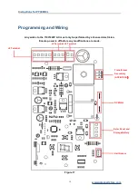
Page 17: ...minal J2 Terminal Transformer Secondary AC24V 3 3A Programming and Wiring Any works to the 110V 220V AC must only be performed by a licensed electrician Ensure power is off before any modifications ar...

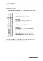
Page 18: ...MP Alarm Lamp 24VDC Terminal LAMP Alarm Lamp 24VDC J3 Terminal Terminal GND Common Terminal for Photocell Terminal PE Photocell Input N C Terminal 24 Additional Accessories 24VDC Additional accessorie...

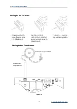
Page 19: ...erminal that you are looking to connect to Refer to Page 13 Tighten with a screwdriver to secure the wire in place Wiring to the Terminal Wiring to the Transformer Figure 18 Using a screwdriver to loo...

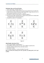
Page 20: ...the digital will dispaly 2 4 Press and hold CLOSE until gate closes to a proper closed position The closed position will be determined by customer themselves 5 Press SET to confirm the closed position...

Page 21: ...lowest level 3 Press SET to confirm the setting Note The sensivity should be set according to the gate weight to ensure the reverse function is workable or it may have potential safety concerns Figur...

Page 22: ...ared Photocell is blocked the gate will stop and reverse immediately to protect user and property security To install photocells connect wiring as per Figure 23 The distance between photocell receiver...

Page 23: ...gate will open 1m wide to allow pedestrian access Single Button Mode Remote Control Figure 24 Remote Control Learning 1 Press CODE button once the red light on digital tube will be on 2 Press the butt...

Page 24: ...0 Clearing Remote Controls To delete all paired remote controls press and hold the button CODE till digital displays C all previously paired remote controls will be deleted Figure 26 Connecting Storag...

Page 25: ...ar charger charger Storage Storage battery battery Control Control board board Figure 28 Maintenance The gate should be checked every month to make sure it operates normally For the sake of safety eac...

Page 26: ...ared port and GND short circuit if connect infrared sensor please make sure the wiring is correct and the photocell is N C 3 Make sure that the photocell mounting position can be mutually aligned 4 Re...

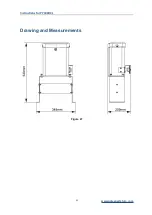
Page 27: ...Instructions for PY300DCL www gatexpertstore com 23 Drawing and Measurements Figure 27...

Reviews: