background image

TIRE CHANGER FOR TRUCK TWC-1600

1

1 GENERAL INFORMATION

Tire changer has been specifically designed to demount high-speed bus and

truck tires with rims form 14"to 26"and a maximum 1600mm diameter

Any other use is improper and therefore not authorized before beginning any

kind of work on or with this machine, carefully read and understand the

contents of these operating instructions.

Shall not liable for any injury to persons or damage to things caused by

improper use of this machine.

Keep this manual near the machine and consult it as needed during

operations.

2 TECHNICAL DATA

Pump motor

1.5KW

Gear-box motor

1.8KW

Handles rim form

14"-26"

Max. wheel diameter

1.600mm

Max. wheel width

780mm

Weight(with standard accessories)

518kg

Acoustic pressure level(at work)

L

PA<70dB(A)

3 GENERAL SAFETY REGULATION

The use of this machine is reserved to specially trained and authorized

personnel.

Any unauthorized changes or modifications to the machine, in particular to its

electrics system, relieve form all liability.

Removing or tampering with the safety devices installed on this machine is in

violation of European safety Regulations.

4 SAFETY DEVICES

Tire changer has a number of safety devices designed to guarantee the utmost

operator safety:

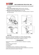
1.

Check valve on the spindle opening hydraulic line

(inside the swivel

connector, see fig. B/1).This prevents the wheel form falling form the spindle

if the hydraulic is accidentally broken.

2. pilot operated dual seal check valve(

see Fig. B/2)

This prevents the spindle carrier arm from dropping if the hydraulic circuit

accidentally breaks.

3.

Pressure relief valve factory set at 130 bar ±5%

(see Fig. B/3).

Any work, however minor, on the electric system must
be done exclusively by professionally qualified
personnel.

Summary of Contents for TWC-1600

Page 1: ...TIRE CHANGER FOR TRUCK TWC 1600 AUTOMATIC TIRE CHANGER INSTRUCTION MANULA TIRE CHANGER ITEM NO TWC 1600...

Page 2: ...B A 3 GENERAL SAFETY REGULATION The use of this machine is reserved to specially trained and authorized personnel Any unauthorized changes or modifications to the machine in particular to its electric...

Page 3: ...has been removed CAUTION Removing or tampering with safeties is in violation of European Safety Regulations and relieves manufacturer of any and all liability for injury to persons to damage to things...

Page 4: ...protected by some kind of roofing against rain The following work environment conditions are applicable Relative humidity form 30 95 without condensation Temperature form 0 55 WORKPLACE REQUIREMENTS M...

Page 5: ...set for 30 mA The current in stake is adequately protected against over currents with fuses or automatic magneto thermic switch with rated values as shown in the table Note the required power draw as...

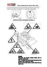
Page 6: ...motor rotation corresponds to the indicating arrow 6 fig B 6 8 IDENTIFYING WARNING SIGNALS WARNING Unreadable and missing warning labels must be replaced immediately Don t interpose any object witch...

Page 7: ...arm of the self centering chuck UN LOCKING The pedal 10 fig c when pressed on the left or right side rotates the self centering chuck in the same direction as shown by the arrows placed on the foot p...

Page 8: ...Fig C the spindle 2 Fig A should turn clockwise depress the left pedal the spindle should turn anticlockwise 4 Check to be certain the hydraulic circuit is working correctly move switch lever 9 Fig c...

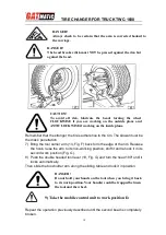
Page 9: ...acelets and too large clothes can be dangerous for the operator 1 Take the mobile control unit to work position B 2 Pull the tool holder arm 14 Fig D into the upright position 3 Operating form the mob...

Page 10: ...wheel until the outside of the rim skims the bead breaker disk fig F 5 Rotate the wheel and at the same time advance the bead breaker plate with small forward movements following the profile of the r...

Page 11: ...he sliding table and lock it in position Repeat the operation previously described until the second bead is completely broken DANGER Always check to be certain that the arm is corrected hooked to the...

Page 12: ...17 Fig I between rim and bead at the right of the tool Press down on the lever and lower the wheel to bring the edge of the rim about 5 cm form the hooked tool Turn the wheel anticlockwise pressing d...

Page 13: ...m the spindle put it back on the spindle as described in the section on CLAMPING THE WHEEL 2 Lubricate both beads and the rim with tire manufacturer recommended lubricant 3 Attach the RP clip to the o...

Page 14: ...rn the second bead begins to slip into the center well 11 When the bead is fully mounted move the tool away form the wheel tip it to its non working position and remove the clip 12 Position the platfo...

Page 15: ...e hook tool is positioned on the wheel side If not press lever 19 Fig D and turn it 180 4 Move the tool forward until the red reference dot is lined up with the outside edge of the rim and about 5 mm...

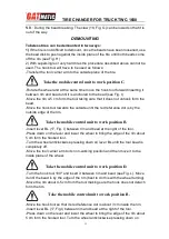
Page 16: ...w all the steps described previously for bead breaking tubeless tires With tubed tires however stop disk movement as soon as the bead has loosened to avoid damaging the tube inflation valve DEMOUNTING...

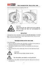
Page 17: ...e lever and lower the wheel to bring the edge of the rim about 5 cm from the hooked tool Turn the wheel anticlockwise pressing down on lever BL until the tire comes completely off the rim MOUNING 1 If...

Page 18: ...the clip 10 Remove the tool from the tire 11 Move the tool carrier arm to its non working position Move it to the outside plane of the tire 12 Turn the tool 180 with lever 19 Fig D 13 Turn the spindl...

Page 19: ...it 21 Pull back on this lever which will guide the bead into center well Continue to turn the spindle until the tire is completely mounted on the rim 22 Tip the tool carrier arm to its non working po...

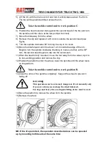
Page 20: ...this time bring the disk against the split ring see Fig Z until the lock ring is freed Remove this with the special lever TL 19 Fig Z or with the help of the disk 7 Remove the split ring 8 Move the t...

Page 21: ...peration but this time move the disk against the split ring see Fig Z until the locking ring is released This ring can be removed with the special TL lever 19 Fig Z or with the help of the bead disk 6...

Page 22: ...ly off the split ring MOUNTING WHEELS WITH 3 PIECE SPLIT RINGS 1 Move the tool carrier arm to its non working position If the rim has been removed from the spindle put it back on the spindle as descri...

Page 23: ...e wheel WHEELS WITH 5 SEGMENT SPLIT RINGS 1 Move the tool carrier arm to its non working position If the rim has been removed from the spindle put it back on the spindle as described in the section on...

Page 24: ...ft cylinder from time to time and also its swivel Add the grease through the grease nipples see Fig J using ordinary lubricating grease NB To reach the grease nipple on the bracket remove the plastic...

Page 25: ...having switched the general button on the electric pack the general warning light does not light on and no control can function After having switched the general button on the general warning light a...

Page 26: ...all the parts that could be damaged if they dry out the chuck the slot of the tool holding arm the slides of the carriage the tool Empty oil hydraulic fluid reservoirs and wrap the machine in a sheet...

Reviews: