30
8. Mechanics Setup
Take the manufacturer’s manual with the assembly sketches and start assembly of your quadrocopter according to the
drawings starting on page P.1.
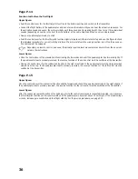
Page P.1
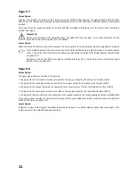
Upper figure:
Insert the four round magnets into the four hood holders and glue the magnets on with liquid instant adhesive.
Lower figure:
Install the four landing gear legs according to the figure. The upper plastic rings may be secured additionally with a little
adhesive.
After assembly, check the spring function and apply some oil into the penetration bores of the chassis holder if required.
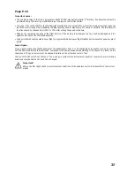
Page P.2
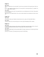
Upper figure:
Install the boom arms according to the figure. Observe the different screw lengths and use medium-hard threadlocker
varnish for each metal screw connection.
Attention, important!
Do not insert the motor carrier plate between the side plates swapped! Work precisely according to the manufac-
turer’s drawing and observe the correct position of the bores for the motor attachment screws during assembly.
Lower figure:
After correctly installing the four boom arms, glue the motor carrier plate to the side parts. Use liquid instant adhesive
applied to the inner edges of the components.
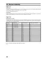
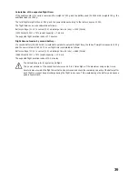
Page P.3
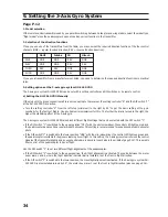
Upper figure:
Screw the 8 spacer bolts to one of the two chassis plates according to the figure. Use low-hardness threadlocker varnish.
Important!
The two square chassis plates have a larger number of bores on one side. Adhere to the manufacturer’s drawing
precisely and use the correct screw bores for assembly of the spacer bolts.
Lower figure:
Insert the four boom arms onto the chassis plate with the spacer bolts. Align the plate so that the side with the larger
number of bores is on the left.
Important!
When putting on the second chassis plate, observe the the side with the larger number of bores is also on the left.
Use low-hardness threadlocker varnish again when screwing on the second chassis plate.

