35
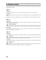
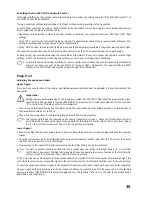
b) Setting the GU-344 GYRO by Remote Control
If the plug with the green connection cable is connected to the receiver, the setting controller “A” and the DIP switch “1” at
the GU-344 GYRO are deactivated.
The gyro sensitivity settings and switching of the flight settings are only possible via the transmitter.
A switch, slider or dial can be used as control encoder at the transmitter; it must be coupled to the corresponding receiver
output (plug with the greed connection cable).
• Depending on the direction in which the control encoder is operated, you may switch between “CRU” and “HOV” flight
settings.
In the “CRU” position, the control LED lights up red and the quadrocopter behaves like a regular model helicopter. This
setting is recommended for experienced model helicopter pilots.
• In the “HOV” position, the control LED lights up green and the quadrocopter is suitable for beginners learning hover flight.
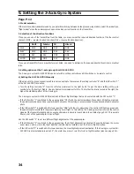
The required gyro sensitivity can be set at the remote control using the EPA or travel function (servo path limiter).
As basic setting, we recommend reducing the servo path on either side of the control encoder, and therefore for both flight
settings, to 50%. By increasing or reducing the set value, you may set an individual gyro sensitivity.
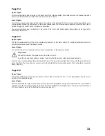
In contrast to manual setting, switching by remote control will not reduce the countersignals of the transmitter
and also not apply any expo share (see sketch at the lower right). On demand, the required EPA and EXPO
settings of the control channels must be performed right at the transmitter.
Page P.13
Adjusting the speed controllers
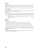
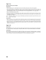
Upper figure:
For correct and even function of the motors, each individual speed controller must be adjusted to the control signals of the
transmitter.
Important:
Setting requires decommissioning of the 3-axis gyro system GU-344 GYRO. Disconnect the plug with the green
cable for the landing gear/gyro function (GEAR/GAIN) from the receiver if it was connected and turn the controller
“A” to the left stop (minimum) with a mini screwdriver.
• Then switch on the transmitter and set the trimming function of all channels to the middle position. The throttle path at
the transmitter should be set to 100%.
• Then move the control lever for the throttle/pitch function to the top-most position.
The figures on this and the following pages show a transmitter in mode 1, where the throttle/pitch control is
performed with the right control lever. If you operate the throttle/pitch control with the left control lever (modes
2 or 4), the left control lever must be put in the top position accordingly.
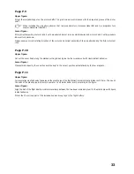
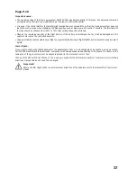
Lower figure:
• Connect the flight battery to the quadrocopter. The motor issues three sounds in increasing height and then two separate
sounds.
• Move the control lever for the throttle/pitch function to the bottom-most position right after this. The motor then emits
two brief and a longer tone after a short break.
• Programming to the transmitter signal is completed and the flight battery can be disconnected.
If a sixth or seventh sound is emitted after the 5 sounds upon connection of the flight battery (2- or 3-cell LiPo
flight battery), disconnect the flight battery again at once and operate the reverse function of the throttle/pitch
control lever at the transmitter. Then repeat the teaching process.
If the motor issues a quick sequence of brief sounds without interruption after the three sounds of increasing height, the
controller did not review any transmitter signal or the control lever for the throttle/pitch function is not in the end position.
To see if the speed controller has taught in the transmitter signals correctly, teach in each each speed controller separately.
Once you have performed teaching in of all four speed controllers, connect the plug with the green cable for the landing
gear/gyro function (GEAR/GAIN) to the receiver again and turn the controller “A” by 90° to the right to the initial position
again with a mini screwdriver.

