background image

1

Introduction

Thank you for purchasing the Gavita

  Master Controller EL3. This manual describes mounting, installation and how to use 

the product. Mounting and installation of the  Master Controller EL3 may only be executed by certified service personnel. 

Please read and understand this manual completely before using the product. Only use the product as specified in this manual. 

Failure to follow any of these directions for use and/or maintenance for this device will void any warranty on the product and 

the owner will be fully liable for any damages.

1.1 

Used Symbols

Warning! 

 A warning indicates severe damage to the user and/or product may occur when a procedure is not carried 

out as described.

Caution! 

 A caution sign indicates problems may occur if a procedure is not carried out as described. It may also serve 

as a reminder to the user.


Note: 

 A note gives additional information, e.g. for a procedure.

This symbol is an internationally recognized symbol used to designate recyclable materials.

This symbol is an authorized use mark employed on electronic products manufactured or sold in the United States, 

which indicates that the electromagnetic emissions from the device have been measured to be under the limits 

published by the Federal Communications Commission. The FCC logo is a mark that declares that the equipment is 

authorized to market and operate under the FCC’s SDOC procedure.

This symbol shows that a product has been independently tested and certified to meet recognized standards for safety.

 This symbol on material, accessories or packaging indicates that this product may not be discarded as household 

waste. By properly disposing the equipment, you will be helping to prevent possible risks to the environment and public 

health, which might otherwise be caused by improper handling of the discarded equipment. Recycling of materials 

contributes to the conservation of natural resources. Therefore, please do not dispose of old electronics and electrical 

appliances via household waste.

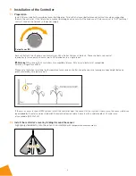
 This symbol indicates the minimum distance (B) between the LED fixture (A) and the lit surface. 

Product description

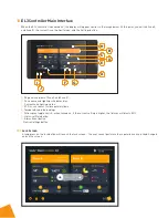
The Gavita Master Controller EL3 is a lighting controller with an 8" LCD touch screen display. Each controller can support up to 

512 e-Series compatible fixtures on two channels.

The EL3 controller helps you control your lights to best suit your plants’ growing needs. With this controller, you can program 

on and off setpoints and build out complete growth schedules that allow you to automate your lights from early veg to late 

flower. When using a compatible fixture (see Fixture Compatibility for reference), you can view their individual performance 

at a granular level. It also lets you pick high-temperature dimming and shutdown setpoints to protect your plants if the room 

temperature exceeds your desired level. An audible alarm can also be activated in the event that a setpoint is exceeded. The 

EL3 can also utilize compatible Titan Controls™ sensors to gather additional environmental information.* A unique feature 

of the EL3 is its data-logging capabilities, which allow you to look at your growing environment’s historical metrics for 

temperature, lighting cycles, humidity, CO

2

,* EC,* VWC, and substrate temperature.*

*This data is gathered when using compatible Titan Controls sensors only (sold separately).

Gavita


 Master Controller EL3

Summary of Contents for Master Controller EL3

Page 1: ...hat this product may not be discarded as household waste By properly disposing the equipment you will be helping to prevent possible risks to the environment and public health which might otherwise be caused by improper handling of the discarded equipment Recycling of materials contributes to the conservation of natural resources Therefore please do not dispose of old electronics and electrical ap...

Page 2: ... FCC Rules This product may cause interference to radio equipment and should not be installed near maritime safety communications equipment or other critical navigation or communication equipment operating between 0 45 30 MHz A simple measure to correct interference is to add ferrites to the ends of power cords and or lengths of communication cables CAUTION Changes or modifications not expressly a...

Page 3: ...n Zone B C Zone A Control the dimming of luminaires in Zone A Attention The original cable provided by the manufacturer must be used to connect to this port D Sensor For compatible Titan Controls Sensors sold separately Attention Do not connect the fixture to the sensor port Use only for the sensor otherwise permanent damage to the sensor and controller may occur E Alarm Switching control of alarm...

Page 4: ...s are sold separately Please visit www gavita com for Gavita s latest products NAME DESCRIPTION SPECIFICATION F T B Zone B temperature detection G T A Zone A temperature detection Attention Only a compatible temperature probe may be used H Dry Contact Output switch signals to control Zone A and Zone B N O 1 Access point for signal line of controlled equipment switch in area B N O 2 Access point fo...

Page 5: ...acez pas l écran LCD dans un environnement chaud ou humide Do not expose the LCD screen to direct sunlight or strong fluorescent light for long periods N exposez pas l écran LCD à la lumière directe du soleil ou à une forte fluorescence trop longtemps Do not wipe the LCD screen with caustic cleaners this may damage the screen N utilisez pas de détergent corrosif pour essuyer l écran LCD car cela l...

Page 6: ...m Warning Only connect EL3 controllers to compatible fixtures For an up to date list of compatible fixtures visit gavita com EL3 Please note that when installing the temperature sensor and controller hang the sensor at average canopy height between plants preferably not against a wall If there is a sensor for your HVAC system install the controller near the sensor for that system If necessary the ...

Page 7: ... 7 9 3 Take the controller and carefully remove the mounting plate from the body Use countersunk screws to secure the mounting plate to the wall 9 4 Connect the luminaire cable to the controller ...

Page 8: ...u can continue setting up the controller 9 6 Once all primary connections have been made reconnect the controller to the wall mount bracket If using accessory output inputs i e Alarm Sens or External Control or Contactors make these connections prior to connecting controller to bracket ...

Page 9: ...d lighting schedule status C Current zone lighting status D VPD or soil sensor sold separately data E Temperature probe readings F Foliar spray toggle switch when turned on if the current setting is higher the fixtures will dim to 50 G Historical Data button H Alarm Event button I Device Settings button 10 1 Lock Screen A long press on the lock button will launch the lock screen the user cannot pe...

Page 10: ... the setup page The settings page contains three sub pages Basic Settings Data Transfer and System Tools 10 3 Basic Settings 10 4 Time Setting Time Setting Click the time and scroll up and down in the pop up box to select the current time Click the Confirm button to save the time or click Cancel ...

Page 11: ...witch to a low light state when there is no user interaction within the user determined timeframe When tapped again it will return to the original screen brightness 10 8 Temperature Format Setting The default mode is Fahrenheit The EL3 can display temperatures in Fahrenheit or Celsius 10 9 Dark Mode The default mode is dark mode Switch between light and dark mode by sliding the button 10 10 Screen...

Page 12: ... sound until the cause has been fixed 10 12 Data Transfer Import Upload settings from another EL3 for quicker installation and setup when using multiple units Export Plugin the USB flash drive to export zone settings and growth plans to sync with other EL3s 11 Sytem Tools 11 1 System Capacity Displays the current total storage space and free space for the EL3 ...

Page 13: ... interface 2 The light is always off and the front and rear lights are normal Check the light input interface 3 The light is always off but the light behind it is always on Check the cable between the fixture and the previous fixture 11 3 Software Updates The user can update the EL3 to take advantage of new features and capabilities These updates can be found on https gavita com EL3 Using the incl...

Page 14: ... digital certificates used by the APK 11 7 Zone Management After the EL3 controller is powered on and enters the home screen the settings and readings for Zone A and Zone B will be displayed Select Zone A or Zone B and the home screen will display that zone Fixture List Sensor List Growth Schedule Historical Data and Zone Settings are displayed on the left hand side of the screen the Home button a...

Page 15: ...0e Gavita 2400e Legacy Fixtures Gavita 900e Gavita 1700e Sun System HPS Gavita HPS and other A user defined option for fixtures that are not Gavita or Sun System branded Use at own risk 11 9 Fixture Search This feature is for Intelligent Fixtures only Click on the fixture to find it this will clear the current device list will be cleared and all fixtures in the current area will be automatically s...

Page 16: ...splayed by the Substrate Sensor EC VWC and substrate temperature Data displayed by the 3 in 1 VPD Sensor VPD temperature and humidity 1 Click on the tab for the 3 in 1 Sensor to go to the sensor s Detailed Information page This page allows you to name the sensor assign it to a zone locate the sensor and add it to the home page Click the Zone button to switch the location of the sensor ...

Page 17: ...ick OK and the sensor will switch to Zone B When the sensor is in Zone B click OK and the sensor will switch to Zone A Sensor Locating Click OK and the indicator on the sensor will start flashing Use it to confirm the physical location of the sensor ...

Page 18: ...ors to go to the sensor details page This page allows you to name the sensor position it locate it switch the substrate calibration and add it to the home page Substrate switching Switch soil sensor to substrate being used CocoPro or Stonewool ...

Page 19: ...different growth cycles Once the plan is created click Next to go to the plan setup page 3 Set schedule From the schedule setting page set brightness at different times to simulate sunrise and sunset Time cycle settings can also be added or deleted View or edit each schedule s brightness and time cycle from the schedule setting homepage Click on Edit to access the schedule settings Click on Edit C...

Page 20: ...ht history display on or off Browse one day three days or seven days of history by selecting the time above or use the calendar to select the desired timeframe Use the Export CSV function to export history to a USB flash drive Insert the USB flash drive to use this function 12 4 Zone Settings Enter the Setting interface to view Alarm Dry Contact Control External Control Foliar Spray Temperature Se...

Page 21: ...m Low humidity Low humidity reading from the VPD sensor generates an alarm High temperature Excessive temperature reading from the VPD sensor generates an alarm High humidity High humidity reading from the VPD sensor generates an alarm VDP range If the VPD value is outside the preset range an alarm will be generated Soil Sensor Alarm Soil sensor disconnect alarm Generates an alarm when soil sensor...

Page 22: ...g the lighting schedule i e if the lighting is on the contactor is closed if the lighting is off the contactor is open External Control Activation This depends on the external input voltage that the current contactor operates at i e if the current external input voltage is 3 5V the contactor closes and if the current external input voltage is 3 5V the contactor opens Foliar Spray Automatic Sprayin...

Page 23: ...en the lighting schedule is activated the contactors close synchronously In this case an external device such as a CO2 generator can be turned on for photosynthetic purposes When the strategy is switched off the external control devices are switched off 12 7 External Control This section is a configuration switch for external third party inputs When this is turned on the EL3 can be controlled by t...

Page 24: ...e purchase of third party products without our permission 14 Troubleshooting Q EL3 does not start A 1 Please check if the power adapter is working correctly 2 Please make sure the 110 220V AC power supply is normal Q The user has set and activated the lighting schedule correctly but the light does not turn on A 1 Check whether the temperature sensor in the current zone is plugged in 2 Third party ...

Reviews: