


™
2
3
Product information and specifications
3.1
General product information
Product name
Gavita™ Master Controller EL3
Manufacturer
Hawthorne Hydroponics LLC
Part number
HGC906174
UPC
849969000436
3.2
Technical specifications
Adapter Input:
100-240 V, 50/60 Hz 1.5 A
Controller Input:
15 Vdc, 3 A
Certified / Authorized:
ETL, FCC
Enclosure protection level:
IP20
Maximum cascade distance:
800m
Maximum number of luminaires:
512 (256 per zone)
Number of sensors that can be carried
16
Temperature range:
32-122°F (0-50°C)
Working environment:
Humidity ≤ 90%
External dimming analog output accuracy:
1%
Operating temperature:
32-122°F (0-50°C)
Temperature accuracy:
±0.54°F (T-A, T-B)
Weight:
3.75 lb
Dimensions:
L: 9.84 in x W: 5.41 in x H: 1.38 in
Warranty:
3 year
This device complies with Part 18 of the FCC Rules. This product may cause interference to radio equipment and should not be
installed near maritime safety communications equipment or other critical navigation or communication equipment operating
between 0.45-30 MHz. A simple measure to correct interference is to add ferrites to the ends of power cords and/or lengths of
communication cables.
CAUTION
– Changes or modifications not expressly approved by the party responsible for compliance could void the user's
authority to operate the equipment.
4
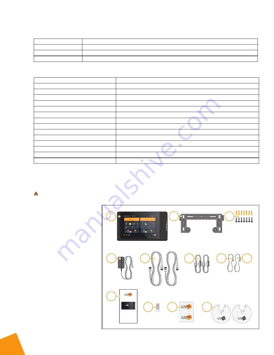
Contents (What’s
included in the box)
A.
1 x Gavita™ Master Controller EL3
B.
1 mounting plate
C.
7 x (expandable tube self-tapping
screws)
D.
1 x power adapter
100-240V Ac/DC 15V@3A
E.
2 x 5m luminaire cables
F.
2 x 5m temperature probes
G.
1 x 610mm RJ10 4P4C cable-1
H.
1 x 610mm RJ10 4P4C cable-2
I.
1 x Quick Start Guide
J.
1 USB flash drive (8 GB)
K.
2 x LOGO stickers
L.
2 x caps
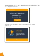
Quick Instruction
Gavita
Master
Controllers
EL3
Quick Instruction Guide
®
®
A
D
I
J
K
L
E
F
G
H
B
C


