


™
4
7
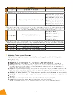
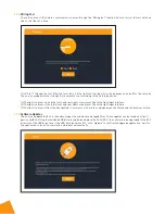
Lighting Fixtures and Sensors
Lighting fixtures and digital sensors are sold separately. Please visit www.gavita.com for Gavita's latest products.
Safety Precautions
Warning!
Keep the controller away from fire, excessive heat, water, dust, and contamination.
Attention! Gardez le contrôleur loin du feu, de la chaleur excessive, de l'eau, de la poussière et de la contamination
Warning!
The Gavita Master Controller EL3 should only be used to control compatible Gavita e-Series ballasts. Do
not connect the controller to other products, as this can be dangerous and may cause the connected equipment to
malfunction. Doing so will void the warranty.
Attention! Le contrôleur Gavita Master EL3 ne peut être utilisé que pour contrôler les ballasts compatibles de série électronique
Gavita.Ne connectez pas le contrôleur à d'autres produits car cela peut être dangereux et peut causer des défaillances dans
l'équipement connect é. Cela annulera la garantie.
Warning!
Do not open or disassemble the controller; there are no serviceable parts inside. Opening the controller will void
its warranty.
Attention! Ne pas ouvrir ou désassembler le contrôleur, il ne contient pas de pièces serviceables. Ouvrir le contrôleur annulera
sa garantie.
Warning!
Make sure the signal wires do not touch the reflectors. The reflectors can get very hot.
Attention! Assurez-vous que les câbles de signal ne touchent pas les réflecteurs. très chauds.
Lighting fixtures and digital sensors are sold separately. Please visit www.gavita.com for Gavita's latest products.
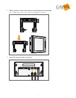
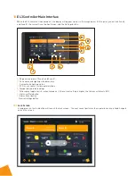
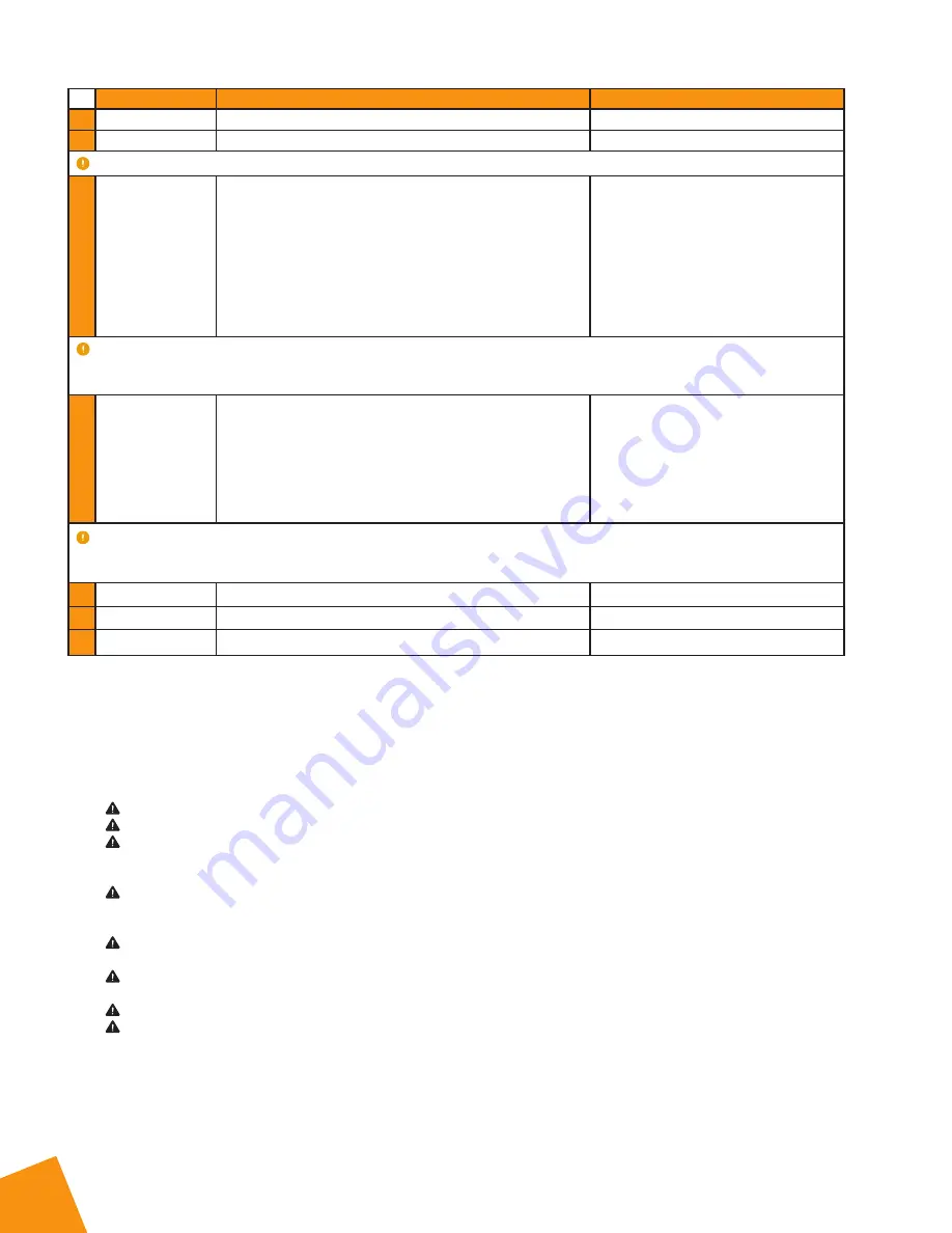
NAME
DESCRIPTION
SPECIFICATION
F:
T-B
Zone B temperature detection
•
G:
T-A
Zone A temperature detection
•
Attention:
Only a compatible temperature probe may be used.
H:
Dry Contact
Output switch signals to control Zone A and Zone B
N/O 1)
Access point for signal line of
controlled equipment switch in area B
N/O 2)
Access point for signal line of
controlled equipment switch in area B
N/O 3)
Access point for signal line of
controlled equipment switch in area A
N/O 4)
Access point for signal line of
controlled equipment switch in area A
Attention:
The port output is a switching signal (no positive or negative polarity) and does not have voltage/current drive
capability. If voltage and current are applied to the port, the nominal switching capacity should not exceed: 1A 30V DC,
0.3A 125V AC (resistive load). The original cable provided by the manufacturer must be used to connect to this port.
I:
0-11.5V Input T
Dimming and switching of third-party
input control connections
I/P 1.1 B-
Ground Zone B
I/P 1.2 B+
0-11.5V DC Zone B
I/P 1.3 A+
0-11.5V DC Zone A
I/P 1.4 A-
Ground Zone A
Attention:
The input should be a voltage signal and will not recognize current signals; VPP of the input voltage should
be less than 200mV; otherwise, it may cause the EL3 external dimming accuracy to error at more than 1%. The original
adapter provided by the manufacturer must be used and no adapter from other manufacturers should be used.
J:
Debug Port
Used only by Tech Support
•
K:
Reset Key
Used to reset EL3 to factory settings
•
L:
USB Port
Used to import/export setting as well as update firmware
•


