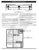
FIG. 15
10
PREVENTIVE MAINTENANCE
PREVENTIVE MAINTENANCE
The following should be checked periodically in order to keep
The Gaylord Ventilator operating at design efficiency:
Weekly
1. The detergent tank should be checked at least weekly and
kept full with a recommended detergent. (Refer to Page 12)
Monthly
1. The detergent system fittings should be checked at least
monthly. This is an airtight system and fittings should be
tight. (For complete details refer to the Detergent Pump
section on Page 12.)
2. At least monthly, at the conclusion of a wash cycle, open
the inspection doors of the ventilator and check to ensure
that the interior has been cleaned of grease, dust, and lint.
(Refer to Figure 15) If overall cleaning appears to be
inadequate, refer to “Trouble-Shooting of the Wash Sys-
tem”, Page 19.
3. The main grease gutter of the ventilator should be checked
at least monthly to remove any foreign material such as
paper towels, order chits, etc.
Every Six Months
1. Exhaust fan(s) should be checked every six months for belt
tightness, belt alignment, and lubrication of necessary
moving parts.
NOTE: A blue lithium based grease is best suited for high
heat and speed bearing lubrication.
2. Check for proper velocity at air inlet slot. Refer to Pages 22
through 24 for method of checking velocity.
3. Test the "Internal Fire Mode" (electrically activated
dampers only) to check for proper damper closure. Refer
to page 5. Reset damper when test is complete.
4. Detergent tank and foot valve should be cleaned every six
months.
NOTE: Annual and semi-annual inspections are
recommended by the NFPA, Standard No. 96, Chapter 8.
Factory trained service agencies are certified by Gaylord
Industries, Inc. to perform these inspections. For the name
and phone number of your nearest agent call 1-800-547-9696.
E
L
U
D
E
H
C
S
N
O
I
T
C
E
P
S
N
I
M
E
T
S
Y
S
T
S
U
A
H
X
E
s
n
o
i
t
a
r
e
p
o
g
n
i
k
o
o
c
l
e
u
f
d
il
o
s
g
n
i
v
r
e
s
s
m
e
t
s
y
S
y
l
h
t
n
o
M
s
a
h
c
u
s
s
n
o
i
t
a
r
e
p
o
g
n
i
k
o
o
c
e
m
u
l
o
v
-
h
g
i
h
g
n
i
v
r
e
s
s
m
e
t
s
y
S
g
n
i
k
o
o
c
k
o
w
r
o
g
n
il
i
o
r
b
r
a
h
c
,
g
n
i
k
o
o
c
r
u
o
h
-
4
2
y
l
r
e
t
r
a
u
Q
s
n
o
i
t
a
r
e
p
o
g
n
i
k
o
o
c
e
m
u
l
o
v
-
e
t
a
r
e
d
o
m
g
n
i
v
r
e
s
s
m
e
t
s
y
S
y
ll
a
u
n
n
a
i
m
e
S
s
a
h
c
u
s
,
s
n
o
i
t
a
r
e
p
o
g
n
i
k
o
o
c
e
m
u
l
o
v
-
w
o
l
g
n
i
v
r
e
s
s
m
e
t
s
y
S
r
o
i
n
e
s
r
o
,
s
e
s
s
e
n
i
s
u
b
l
a
n
o
s
a
e
s
,
s
p
m
a
c
y
a
d
,
s
e
h
c
r
u
h
c
s
r
e
t
n
e
c
y
ll
a
u
n
n
A
INSPECTION AND CLEANING REQUIREMENTS
The 1998 edition of NFPA-96 (Standard for Ventilation Control
and Fire Protection of Commercial Cooking Operations)
require that hoods, ducts and exhaust fans be inspected by a
properly trained, qualified and certified company or person(s)
in accordance with the following table.
Upon inspection, if found to be contaminated with deposits
from grease-laden vapors, the entire exhaust system shall be
cleaned by a properly trained, qualified, and certified com-
pany or person(s) acceptable to the authority having jurisdic-
tion in accordance.
When a vent cleaning service is used, a certificate showing
date of inspection or cleaning shall be maintained on the
premises. After cleaning is completed, the vent cleaning con-
tractor shall place or display within the kitchen area a label
indicating the date cleaned and the name of the servicing
company. It shall also indicate areas not cleaned.
Summary of Contents for CG Series
Page 34: ...32 DETERGENT PUMP ...
Page 35: ...33 MISCELLANEOUS VENTILATOR PARTS ...
Page 36: ...34 WIRING DIAGRAM FOR GPC 5000 WITH ELECTRIC FIRE DAMPER 120 VOLT ...
Page 37: ...35 WIRING DIAGRAM FOR GPC 5000 WITH FUSE LINK FIRE DAMPER 120 VOLT ...
Page 38: ...WIRING DIAGRAM FOR GPC 5000 S5 WITH ELECTRIC FIRE DAMPER 120 VOLT 36 ...
Page 39: ...WITH FUSE LINK FIRE DAMPER 120 VOLT WIRING DIAGRAM FOR GPC 5000 S5 37 ...
Page 40: ...WIRING DIAGRAM FOR GPC 5000 WITH ELECTRIC FIRE DAMPER 220 VOLT 38 ...
Page 41: ...WITH FUSE LINK FIRE DAMPER 220 VOLT WIRING DIAGRAM FOR GPC 5000 39 ...
Page 42: ...WIRING DIAGRAM FOR GPC 5000 S5 WITH ELECTRIC FIRE DAMPER 220 VOLT 40 ...
Page 43: ...WITH FUSE LINK FIRE DAMPER 220 VOLT WIRING DIAGRAM FOR GPC 5000 S5 41 ...
Page 46: ......

