A Subsidiary of Gaylord International, Inc.
TUALATIN, OR 97062-8549
FAN ON
FIRE
WASH ON
START
WASH
START
FAN
OPERATING INSTRUCTIONS
1. Push Start Fan before turning on cooking equipment.
2. At the end of the day, or whenever cooking is com-
pleted, push Start Wash. This will turn off the exhaust fan
and begin a timed wash cycle.
NOTE:
24 hour kitchens
must push Start Wash at least once a day or as needed
for proper cleaning.
3. To set the length of time for the wash cycle, open this
cabinet door and set the toggle switches for either Light-
duty, Medium or Heavy-duty cooking equipment.
Extreme cooking loads may require more than one wash
cycle per day.
NOTE:
If the Command Center is a S, TC or RSPC Series,
refer to additional operating instructions inside this panel.
COMMAND CENTER
C-5000-S-TC
MODEL
LOW DETERGENT
1. If Wash On light flashes detergent is low.
FIRE CONDITION
1. A flashing fire light indicates the control is in an
External Fire
Mode
-
exhaust fan on, fire damper open, and water wash
nozzles on.
2. A solid fire light indicates the control is in an
Internal Fire
Mode
-
exhaust fan off, fire damper closed, and water wash
nozzles on.
GAYLORD INDUSTRIES, INC.
WASH TIMES
SWITCH POSITION
3 MIN. LIGHT-DUTY COOKING EQUIPMENT
UP
5 MIN. MEDIUM-DUTY COOKING EQUIPMENT
CENTER
9 MIN. HEAVY-DUTY COOKING EQUIPMENT
DOWN
START
FAN
START
WASH
FAN ON FIRE
WASH ON
CANCEL
SWITCH
FIRE
TEST
SWITCH
WASH 1 WASH 2 WASH 3 WASH 4 WASH 5 WASH
DELAY
MFG. BY:
GAYLORD INDUSTRIES, INC.
P.O. BOX 1149
TUALATIN, OR 97062
MODEL NO. ______________
VOLTAGE ________________
FORM NO. C5CA
FORM NO. C5CB
DELAY TIMES
1 MIN.
SHORT
15 MIN.
MEDIUM
30 MIN.
LONG
IF LIGHT FLASHES DETERGENT
IS LOW
C-5000-S-TC
120vac
13
MODEL C-5000 SERIES COMMAND CENTER - INSTRUCTIONS
MODEL C-5000 SERIES COMMAND CENTER -
GENERAL
The Model C-5000 Series Command Center controls all of
the functions of the Gaylord Water-Wash Ventilator.
The C-5000 Series Command Center is available in four
basic models. They are:
Model
Description of Operation
C-5000 ...................... Manual start fan and start wash
C-5000-TC ................ Programmable time clock opera-
tion of the start fan and start wash
functions
C-5000-S .................. Manual start fan and start wash
functions with sequence wash
feature
C-5000-TC-S ............ Programmable time clock opera-
tion of the start fan and start wash
functions with sequence wash
feature
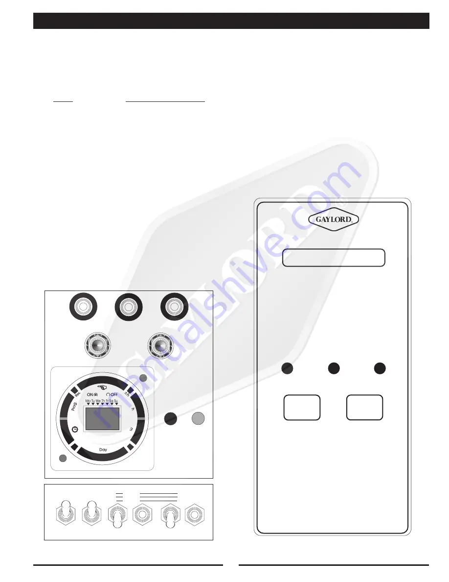
The model number of your control is indicated on the
Command Center label. Refer to Figure 17.
STARTING THE FAN AND WASH CYCLE
The Model C-5000 and C-5000-S Command Centers start
fan and start wash functions are the same. To start the
exhaust fan push the “Start Fan” button and to start the
wash cycle push the “Start Wash” button. The exhaust fan
automatically shuts off when the “Start Wash” button is
pushed.
Models C-5000-TC and C-5000-TC-S include a time clock
which can be programmed to start the fan and wash cycle at
any desired time. (Refer to programming instructions on
Page 15.) However both of these Command Centers may
also be operated manually by pushing the “Start Fan” or
“Start Wash” buttons.
SETTING WASH CYCLE TIME FOR MODELS C-5000
AND C-5000-TC COMMAND CENTERS
To set the length of the wash cycle, open the electrical
compartment. At the bottom of the control chassis is a three
position toggle switch labeled Wash 1 (refer to Fig.17). Set
the toggle switch for either 3, 5 or 9 minutes for light, medium
or heavy duty equipment as required (refer to “Recom-
mended Wash Time” chart on page 14 . Upon activation of
the wash cycle, the detergent injected hot water will wash the
interior of the extraction chamber for the length of time
selected and then shut off.
FIG.17
FIG.18
Summary of Contents for CG Series
Page 34: ...32 DETERGENT PUMP ...
Page 35: ...33 MISCELLANEOUS VENTILATOR PARTS ...
Page 36: ...34 WIRING DIAGRAM FOR GPC 5000 WITH ELECTRIC FIRE DAMPER 120 VOLT ...
Page 37: ...35 WIRING DIAGRAM FOR GPC 5000 WITH FUSE LINK FIRE DAMPER 120 VOLT ...
Page 38: ...WIRING DIAGRAM FOR GPC 5000 S5 WITH ELECTRIC FIRE DAMPER 120 VOLT 36 ...
Page 39: ...WITH FUSE LINK FIRE DAMPER 120 VOLT WIRING DIAGRAM FOR GPC 5000 S5 37 ...
Page 40: ...WIRING DIAGRAM FOR GPC 5000 WITH ELECTRIC FIRE DAMPER 220 VOLT 38 ...
Page 41: ...WITH FUSE LINK FIRE DAMPER 220 VOLT WIRING DIAGRAM FOR GPC 5000 39 ...
Page 42: ...WIRING DIAGRAM FOR GPC 5000 S5 WITH ELECTRIC FIRE DAMPER 220 VOLT 40 ...
Page 43: ...WITH FUSE LINK FIRE DAMPER 220 VOLT WIRING DIAGRAM FOR GPC 5000 S5 41 ...
Page 46: ......

