Chapter 3 - Daily Operation, Page 3-4_______________________________________________________
Starting the Exhaust Fan – Cont.
Figure 3-4-1
Typical Command Center
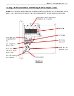
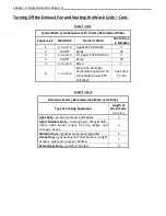
Figure 3-4-2
Typical Wash Control Cabinet
Figure 3-4-3
UV Status Lights
Located on Each Ventilator Section
Figure 3-4-4
ESP Cell Status Light
Located on Wash Control Cabinet
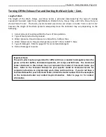
Important Note:
The Command Center illustrated in this manual may not represent the model of Command
Center you have. Refer to the Technical Manual for your specific model of Command Center
for complete instructions on programming wash times. If you do not have a Technical
Manual for your Command Center, obtain the model number from the nameplate on the
Command Center and contact Gaylord Industries. Refer to page 1-1 for contact information.


