Chapter 6 –Testing and Repair, Page 6-2_____________________________________________________
Measuring Airflow – Cont.
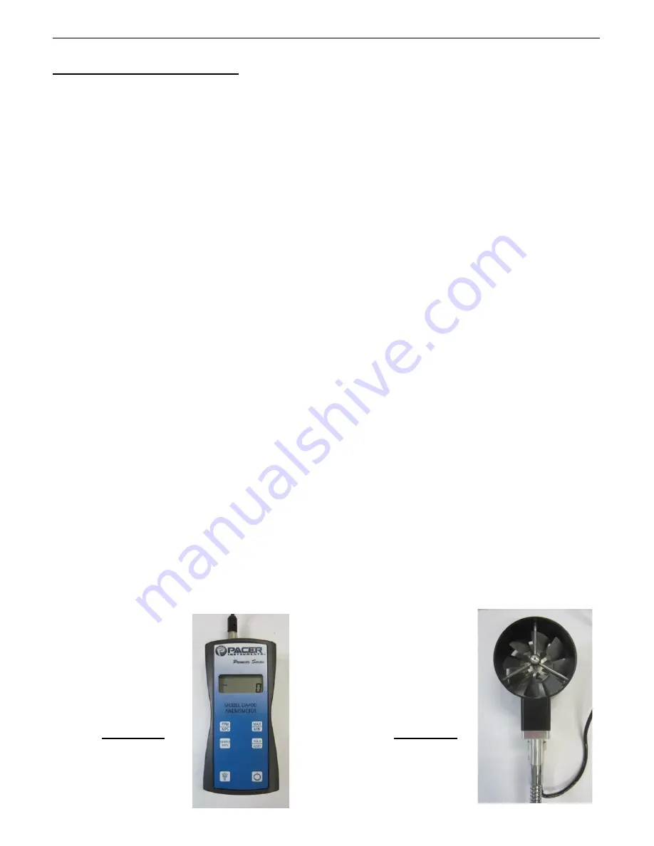
The standard instrument used for measuring the inlet velocities on a Gaylord Ventilator is a Pacer, Model
DA40 or DA400 Digital Anemometer. This instrument is the easiest, most accurate and the best suited
for measuring the Ventilator inlet slot velocities.
Instructions
To measure the air inlet velocity and confirm the exhaust volume, proceed as follows:
1.
For safety purposes turn off the cooking equipment and allow to cool.
2.
Confirm that all Particulate Separators are clean and in place.
3.
Close all Extractor Inspection Doors.
4.
Make sure all UV Module Access Doors are closed.
5.
Turn on the exhaust fan.
6.
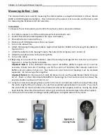
Attach the Sensing Probe guide bracket, Gaylord Part Number 18408, to the Sensing Probe (Refer to
Figure 6-23-1).
7.
Attach the cable from the Sensing Probe to the meter (refer to Figures 6-2-1 and 6-2-2)
8.
Attach the handle sections to the Sensing Probe.
9.
Turn on the meter.
10.
Beginning at one end of the Ventilator, place the sensing head against the inlet slot as shown in
Figure 6-3-1. Allow the meter to stabilize.
Important Note 1:
If the Ventilator includes Custom Air Baffles (Refer to Figure 6-3-1) it will be
necessary to take two sets of readings, one for the section of Ventilator that includes Custom Air
Baffles and one where it does not. Non Custom Air and Custom Air readings must be recorded
separately. Do not average them together.
Important Note 2:
On the rear slot of a BDL-DS Series, do not use the guide bracket (Refer to Figure
6-3-2). There is a Rear Slot Adjustable Baffle for balancing the front and rear slots to achieve the
desired velocities as shown in Chart C-6-4-2.
11.
Using the 16 second averaging feature (refer to the meter instructions) slide the Sensing Probe along
the entire length of the slot, slowly, at a rate that would last approximately 16 seconds. If you reach
the end of the Air Inlet Slot before the 16-Second interval has elapsed, continue moving the probe
head back the other direction (without removing it) until the 16-Second sample interval has expired.
12.
At the end of 16 seconds an average velocity will appear on digital readout of the meter.
Figure 6-2-1
Meter
Figure 6-2-1
Sensing Probe


