Chapter 6 – Testing and Repair, Page 6-20___________________________________________________
Replacing UV Ballast – Cont.
Overview
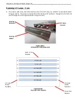
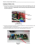
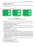
There are three Ballasts in an UV Module. Each Ballast serves two lamps. The left Ballast serves Lamps
#1 and #2, the middle Ballast serves Lamps #3 and #4, and the right Ballast serves Lamps #5 and #6
(Refer to Figure 6-14-1 and 6-15-1). There are a maximum of two UV Modules in one Ventilator section
(Refer to Table T-6-7-1. If one or more Ballast has failed, in the group of SYSTEM STATUS lights mounted
on the Ventilator, the UVi SYSTEM ON green light and the UVi LAMP FAILURE yellow light will be on
indicating one or more Ballast(s) must be replaced (Refer to Figure 4-4-1).
How to Determine Which Ballast is Defective
To determine which Ballast is defective, proceed as follows:
1.
Turn on the power to the Command Center.
2.
Turn on the circuit that supplies power to the UV Lamps.
3.
Push the
START FAN
button on the Command Center.
4.
Open the UV Module Access Door(s).
5.
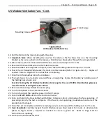
Push and hold in the Door Safety Switch (Refer to Figure 6-21-1) and look at the UV Monitoring
Status Board on each Module (Refer to Figure 6-20-1).
There is one green light for each of the six
Lamps and the light on the left is for Lamp #1 and on the right is for Lamp #6. If for example green
lights for lamps #1 and #2 are off, most likely the left Ballast, Ballast #1 is defective. If light #3 and #4
are off Ballast #2 is defective, and lights #5 and #6 are off Ballast 3 is defective. Whenever one or
more green lights are off, the red light will be on.
6.
After determining which Ballast is defective, replace using the instructions beginning on page 6-22.
Lamps #1 and #2,
Ballast #1.
Lamps #5 and #6,
Ballast #3.
Lamps #3 and #4,
Ballast #2
Figure 6-20-1
UV Monitoring Status Board


