2-7
Chapter 2 - Principles of Operation
ELXC-UVi Series
Ultraviolet Systems (UV)
Overview
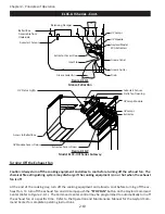
Ventilators incorporating UV Lamps are designated Model ELXC-UVi Series Ventilators. UV Systems are used
to remove a high percentage of grease that the Extractors cannot remove, offering many benefits to the
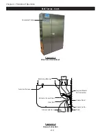
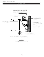
owner/operator. The UV Lamps are mounted in a UV Module which slide into a track downstream (after)
the XGS Extractors (refer to Figure 2-10-1). The electronics and ballasts for UV System are mounted in a UV
Ballast Box which is located on the top of the Ventilator (refer to Figure 2-10-1). The ELXC-UVi Ventilator
is equipped with UV Status Lights to monitor the status of the UV System, and Safety Interlocks to protect
operators from exposure to UV light (refer to Figure 2-8-1).
For proper UV operation, the Ventilators must be maintained in good working order. The UV system must be
inspected periodically and the lamps replaced as necessary. The Ventilator, ductwork and exhaust fan must
be inspected in accordance with NFPA-96 or local guidelines, though frequency of duct cleanings should be
significantly reduced.
UV Safety
Caution: Exposure to UV light is harmful to skin and eyes.
The ELXC-UVi Ventilator is equipped with panels and Safety Interlocks to protect operators from direct expo
-
sure to UV light. All safety precautions called for in this manual must be followed to avoid the potential for
harm to operators or service personnel. Refer to Page 3-3 for complete description of safety precautions.
Turning On the Exhausting Fan and UV System
Caution: Always turn on the exhaust fan before turning on the cooking equipment.
Caution: The chemical fire extinguishing system may discharge if the exhaust fan is not on while the cook-
ing equipment is on or still hot.
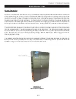
Caution: Never operate the Ventilator without the XGS Extractors in place or the Extractor Access Doors
open (Refer to Figure 2-10-1).
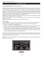
Operation of the exhaust fan and UV Lamps is controlled by the Gaylord Command Center (refer to Figure
2-9-1). To start the exhaust fan and turn on the UV Lamps push the
“START FAN”
button
on the Command
Center. The Command Center control may be programmed to automatically start the exhaust fan at a spe
-
cific time. Refer to the Operation and Maintenance Manual for the Gaylord Command Center for complete
operating instructions of the Command Center.
Note 1:
The ELXC-UVi Series Ventilator may be equipped with a Gaylord Electric Balancing Damper, desig
-
nated “GEBD” in the Ventilator model number, or a Gaylord combination Fire/Balancing Damper, designated
“GFBD” in the model number. The Ventilator model number can be found on the Ventilator Nameplate (Refer
to page 2-19 for information on Balancing Dampers and page 5-11 for a sample of the Nameplate). If the
Ventilator includes one of these dampers, when the fan is started the damper moves from the closed to open
position, and it will take approximately 45 seconds for the exhaust to come up to 100%.
Summary of Contents for ELXC Series
Page 40: ...4 6 INTENTIONALLY LEFT BLANK ...
Page 74: ...7 1 Chapter 7 Wiring Diagrams ELXC GBD with AUTOSTART ...
Page 75: ...7 2 Chapter 7 Wiring Diagrams ELXC GFBD with AUTOSTART ...
Page 76: ...7 3 Chapter 7 Wiring Diagrams ELXC GBD UVi with AUTOSTART ...
Page 77: ...7 4 Chapter 7 Wiring Diagrams ELXC GFBD UVi with AUTOSTART ...
Page 83: ...A 6 INTENTIONALLY LEFT BLANK ...


