2-8
Chapter 2 - Principles of Operation
ELXC-UVi Series - Cont.
Turning On the Exhausting Fan and UV System – Cont.
Note 2:
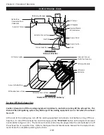
Typically ELXC-UVi Series Ventilators installed in the United States are equipped with a Gaylord Au
-
tostart Controller that automatically turns on the exhaust fan if the temperature at the sensors mounted in
the canopy exceeds 90°F. (Refer to Figure 2-10-1). In some instances Ventilators installed outside the United
States will include an Autostart Control. Inclusion of an Autostart Control is designated by the suffix “
AS
” or
“
DCA
” in the model number. The Ventilator model number can be found on the Ventilator Nameplate (Refer
to page 5-11 for a sample of the Nameplate). Refer to the Operation and Maintenance Manual for the Gay
-
lord Command Center for complete information on the Autostart Control.
Note 3:
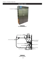
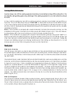
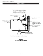
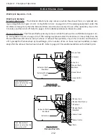
The UV Lamps will not come on unless all the XGS Extractors are in place and the Extractor Access
Doors are closed as shown in Figure 2-10-1 and 2-10-2.
Note 4:
The UV Lamps will not come on unless all the UV Module Access Doors are closed and latched as
shown in Figure 2-10-2.
Note 5:
The UV Lamps will not come on unless the exhaust fan is running.
UV Status Lights
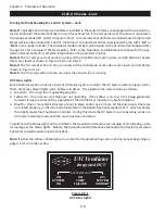
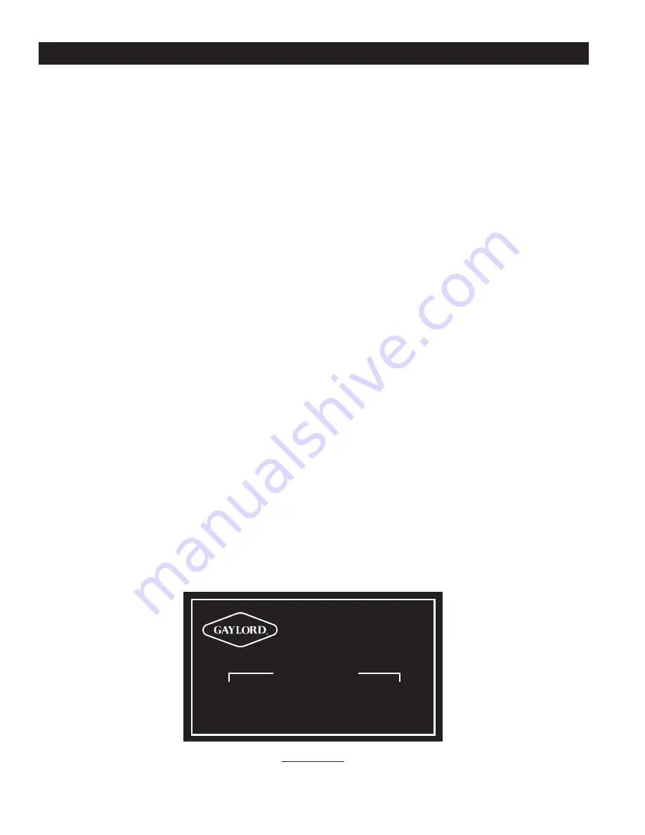
Each Ventilator section contains a bank of UV Status Lights to monitor the UV System (refer to Figure 2-8-1).
There are three colored lights, Blue, Yellow and Green. They indicate the system status as follows:
1.
Green On: The UV system is operating properly.
2.
Yellow On: One or more UV Lamps are not operating. If the yellow is on, less UV is being generated,
however it does not prevent the operation of the Ventilator or indicate an unsafe condition.
3. Blue On: One or more XGS Extractors are not in place and/or one or more UV Module Access Doors are
not closed properly, or the internal temperature of the Ballast Box has exceeded 118° F. which activates
the High Temperature Shutdown Controller. During this mode the UV System is not operating and is in a
UVi System Standby mode until the cause has been corrected.
In addition to the Status Lights on the Ventilator, the Gaylord Command Center displays text indicating a simi
-
lar message as the Status Lights. Refer to the Operation and Maintenance Manual for the Gaylord Command
Center for complete operational instructions.
Note:
If either the Yellow or Blue light are on refer the Troubleshooting section of this manual beginning on
page 4-1 for corrective action.
Figure 2-8-1
UV Status Lights
UVi
SYSTEM
ON
UVi
LAMP
FAILURE
UVi
SYSTEM
STANDBY
20385
SYSTEM STATUS
UVi Ventilator
Integrated DCV
Summary of Contents for ELXC Series
Page 40: ...4 6 INTENTIONALLY LEFT BLANK ...
Page 74: ...7 1 Chapter 7 Wiring Diagrams ELXC GBD with AUTOSTART ...
Page 75: ...7 2 Chapter 7 Wiring Diagrams ELXC GFBD with AUTOSTART ...
Page 76: ...7 3 Chapter 7 Wiring Diagrams ELXC GBD UVi with AUTOSTART ...
Page 77: ...7 4 Chapter 7 Wiring Diagrams ELXC GFBD UVi with AUTOSTART ...
Page 83: ...A 6 INTENTIONALLY LEFT BLANK ...

