3-5
Chapter 3 - Maintenance
UV System Scheduled Preventive Maintenance - Cont.
Test Safety Interlocks for the XGS Extractors
(Pressure Switches) - Cont.
b. Open the Extractor Access Door at the left end of the Ventilator remove one XGS Extractor. The blue
“UVi System Standby” Status Light should come on. If this action does not occur, immediately shut down
the exhaust fan at the Command Center. Refer to the Troubleshooting section of this manual for correc
-
tive action. Repeat tests 3a and 3b for the right most XGS Extractor and again for the center XGS Extrac
-
tor.
c. If there is more than one Ventilator section, repeat tests 3a and 3b for each section.
4.
Test Safety Interlocks for the UV Module Access Panel
(Pressure Switches)
(Caution: For the following tests Polycarbonate Safety Glasses must be worn.)
a.
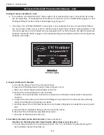
Turn on the exhaust fan at the Command Center. The “UV System On” green Status Light in each
Ventilator Section should be on.
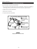
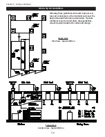
b. Open one UV Module Access Door (refer to Figure 2-10-2). (
Note:
If there are two UV Module
Access Doors always open the shortest door for the test). The blue “UVi System Standby” Status
Light should come on. If this action does not occur, immediately shut down the exhaust fan at the
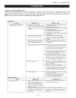
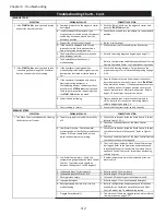
Command Center, refer to the Trouble Shooting section beginning on page 4-3 for corrective
action.
c. If there is more than one Ventilator section, repeat the tests above, 4a and 4b, for each section.
5. Lamp Replacement
The UV Lamps need to be replaced after 13,000 hours of use. After 13,000 hours the Lamps will still work but
the performance of the Lamps decreases dramatically. The Gaylord Command Center has a built-in UV hours
of operation clock. Refer to the Operation and Maintenance Manual for the Gaylord Command Center for
complete operational instructions. If the Lamps have been in use over 13,000 hours they should be replaced.
Refer to Page 5-7 of this manual for detailed instructions for replacing Lamps.
Summary of Contents for ELXC Series
Page 40: ...4 6 INTENTIONALLY LEFT BLANK ...
Page 74: ...7 1 Chapter 7 Wiring Diagrams ELXC GBD with AUTOSTART ...
Page 75: ...7 2 Chapter 7 Wiring Diagrams ELXC GFBD with AUTOSTART ...
Page 76: ...7 3 Chapter 7 Wiring Diagrams ELXC GBD UVi with AUTOSTART ...
Page 77: ...7 4 Chapter 7 Wiring Diagrams ELXC GFBD UVi with AUTOSTART ...
Page 83: ...A 6 INTENTIONALLY LEFT BLANK ...

