4-1
Chapter 4 - Troubleshooting
Troubleshooting
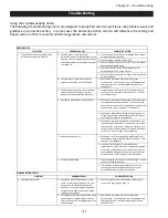
Using the Troubleshooting Charts
The following Troubleshooting Charts are designed to easily find common problems, the probable cause and
guidance on corrective action. In some cases the Corrective Action column will reference the Testing and
Repair section of this manual for additional guidance and actions.
1
1 Check exhaust fan for broken or slipping belts. Adjust
or replace belts as required.
2 Confirm proper rotation of fan wheel.
3 Check for proper size of exhaust fan. Fan must deliver
Ventilator Nameplate rating.
4 Check and adjust Gaylord Balancing Damper as
described pages 2-19
of this manual.
5 Check for open access panel in duct system and close or
re-install if open.
B. Exhaust volume is low due to a heavy
grease accumulation on the Extractors.
1 Remove the Extractors and inspect for grease
accumulation. If the extractors are not being washed
effectively refer to the Troubleshooting section on
WASH CYCLE.
C. The Ventilator must have its own exhaust
system and no other exhaust, such as
dishwasher hoods should be tied into it.
1 Inspect the duct system and verify that there are no
other non Type I Ventilator systems tied in. If so they
must be removed.
D. Improperly placed make-up air diffusers.
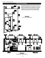
1 Make-up air directed at the Ventilator will likely create
cross drafts disrupting the air flow into the Ventilator.
Adjust the louvers to direct the make-up air away from
the Ventilator. Refer to page 5-5
for guidance.
2 Make-up air should be delivered through registers at
ceiling height, and distributed throughout the kitchen
area. Refer to page 5-5 for guidance.
3 Make-up air registers located near the Ventilator, the
louvers should be adjusted to direct the air away from
the Ventilator. Directing or forcing the make-up air at
the Ventilator typically creates cross drafts resulting in
smoke loss. Refer to page 5-5 for guidance.
E. Inadequate make-up air
1 Make-up air must be supplied for replacement of air
exhausted through all kitchen exhaust systems. Refer
to page 5-5 for guidance.
2 A general "rule of thumb" is that 60% of the
replacement air should be fresh, conditioned, (heated
or cooled) air brought into the kitchen area, with the
remaining 40% allowed to flow into the kitchen from
adjacent areas. Refer to page 5-11 for guidance.
F. Exhaust fan discharge
1 There should be no screen over the discharge. If one is
found, it should be removed.
2 The direction of discharge should not be into the
prevailing winds nor downward onto the roof. A
vertical discharge is highly recommended.
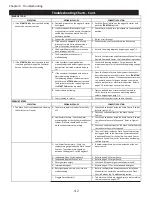
SYMPTOM
PROBABLE CAUSE
CORRECTIVE ACTION
1 Poor grease extraction.
A. Ventilators exhausting too much air can
cause an excessive amount of noise and
allow grease to be pulled through the
Extractors. Ventilators exhausting below
design will also allow grease to be pulled
through the Extractors.
1 Check for proper exhaust volume by following the
instructions beginning on page 5-1.
B. Sticky grease may have accumulated within
the Extractors, creating a higher velocity
within the Extractors allowing grease to be
pulled through.
1 Remove the Extractors and inspect for grease
accumulation. If the extractors are not being washed
effectively refer to the Troubleshooting section on
WASH SYSTEM.
Chapter 4, Page 4-1
PROBABLE CAUSE
SYMPTOM
GREASE EXTRACTION
Exhaust volume is low due to fan
performance issues or a Gaylord Balancing
Damper, is not adjusted properly. Measure
the exhaust volume as described on page 5-
1 through 5-4.
A.
CORRECTIVE ACTION
The Ventilator is not exhausting all the
smoke, heat and grease properly.
SMOKE LOSS
Troubleshooting
Summary of Contents for ELXC Series
Page 40: ...4 6 INTENTIONALLY LEFT BLANK ...
Page 74: ...7 1 Chapter 7 Wiring Diagrams ELXC GBD with AUTOSTART ...
Page 75: ...7 2 Chapter 7 Wiring Diagrams ELXC GFBD with AUTOSTART ...
Page 76: ...7 3 Chapter 7 Wiring Diagrams ELXC GBD UVi with AUTOSTART ...
Page 77: ...7 4 Chapter 7 Wiring Diagrams ELXC GFBD UVi with AUTOSTART ...
Page 83: ...A 6 INTENTIONALLY LEFT BLANK ...


