4-2
Chapter 4 - Troubleshooting
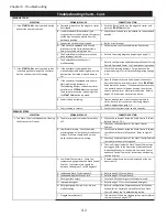
Troubleshooting Charts - Cont.
1 If the
START FAN
button is pushed but the
exhaust fan does not come on.
A. Overload protector on the magnetic starter
has tripped.
1 Push the "Reset" button on the magnetic starter and
push the
START FAN
button.
B. If a HOA (Hands Off/Automatic) type
magnetic starter switch is used, the selector
switch may have been moved from the
automatic position.
1 Check the switch and turn the selector to the automatic
position.
C. Exhaust fan circuit breaker tripped.
1 Re-set circuit breaker.
D. If the system is equipped with a fused
disconnect switch for the exhaust fan, a
fuse or fuses may have blown out.
1 Check continuity of fuses and replace if necessary.
E. The Gaylord Command Center may have
been improperly wired.
1 Refer to the wiring diagrams beginning on page 7-1.
F. The Gaylord Command Center is
malfunctioning.
1
Refer to the Operation and Maintenance Manual for the
Gaylord Command Center, the Troubleshooting section.
2 If the
START FAN
button is pushed and air
is not being pulled through the Ventilator
but you can hear there fan running.
A. If the Ventilator is equipped with a
manually adjustable balancing damper, the
damper may be closed or closed down to
far.
1 Check the balancing dampers. For guidance on the
proper opening refer to instructions beginning on page
2-19.
B. If the ventilator is equipped with either a
electric balancing damper or a
fire/balancing damper, the damper closes
each time the
STOP FAN
button is pushed.
The damper may not be re-opening when
the
START FAN
button is pushed.
1 Open the Extractor Access Panel nearest the exhaust
duct collar and remove the Extractor. Push
START FAN
and observe the damper. If the damper does not move
to a partially open or fully open position then there is
either a mechanical or electrical malfunction. Refer to
page 2-19 instructions on corrective action.
B. Fan drive belt is slipping.
1 Tighten belt and then measure exhaust volume to
verify. Refer to instructions on measuring exhaust
volume beginning on page 5-1.
C. Fan is running in reverse.
1 Contact electrical contractor to wire correctly.
1 The Wash Cycle is not adequately cleaning
the Extractors or Plenum.
A. The water supply is turned off or partially
off.
1 Check the hand valves inside the Wash Control Cabinet.
Refer to Figure 2-15-1.
2 Check any valves upstream of the Wash Control
Cabinet.
B.
1 Check the hand valves inside the Wash Control Cabinet
to make sure they are fully opened. Refer to Figure 2-
15-1
.
2 Check any valves upstream of the Wash Control Cabinet
to make sure they are fully opened.
3 The Line Strainer inside the Wash Control Cabinet may
be clogged. Refer to the Operation, Maintenance and
Installation Manual for the Gaylord Command Center
and Wash Control Cabinet for instructions on cleaning
the Line Strainer.
C. Low Water Temperature - Check the
temperature gauge inside the Wash Control
Cabinet. The temperature should be
between 140 degrees F. to 180 degrees F.
1 If below temperature it must be increased at the hot
water source.
D. Inadequate Wash Cycle frequency.
1 Refer to page 2-15 for guidance.
E. Inadequate length of Wash Cycle.
1 Refer to page 2-15 for guidance.
F. Detergent tank empty.
1 Check and fill the detergent tank at least weekly.
G. Improper detergent.
1 Refer to page 2-17 for recommended detergent.
H. Detergent pump has lost it's prime or is
malfunctioning.
1 Refer to the Operation, Maintenance and Installation
Manual for the Gaylord Command Center and Wash
Control Cabinet, the Troubleshooting section.
I. Clogged Spray Nozzle(s).
1 To determine if there are clogged spray nozzles refer to
the instructions on page 5-25.
PROBABLE CAUSE
CORRECTIVE ACTION
EXHAUST FAN
SYMPTOM
PROBABLE CAUSE
CORRECTIVE ACTION
WASH SYSTEM
SYMPTOM
Low Water Pressure - Check the water
pressure gauge inside the Command Center
cabinet. Pressure should be 40 psi min.
while the Ventilators are washing.
Summary of Contents for ELXC Series
Page 40: ...4 6 INTENTIONALLY LEFT BLANK ...
Page 74: ...7 1 Chapter 7 Wiring Diagrams ELXC GBD with AUTOSTART ...
Page 75: ...7 2 Chapter 7 Wiring Diagrams ELXC GFBD with AUTOSTART ...
Page 76: ...7 3 Chapter 7 Wiring Diagrams ELXC GBD UVi with AUTOSTART ...
Page 77: ...7 4 Chapter 7 Wiring Diagrams ELXC GFBD UVi with AUTOSTART ...
Page 83: ...A 6 INTENTIONALLY LEFT BLANK ...


