4-4
Chapter 4 - Troubleshooting
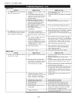
Troubleshooting Charts - Cont.
2
A. One or more UV Lamps has failed
1 Refer to page 5-7 for instructions on determining which
Lamp has failed and replace.
B. UV Ballast has failed.
1 Refer to page 5-14 for instructions on determining
which Ballast has failed and replacing.
C. Loose wires.
1 Check wires 1A and 3A from the Command Center to
the UV Ballast Box. If either are loose, re-secure and
tighten.
3
A. No electrical power to the UV Ballast Box
located on the top of each Ventilator
section.
1 Take steps necessary to supply power to each UV
Ballast Box. Refer to the wiring diagrams in Chapter 7
for voltages.
2 Check the Circuit Breaker.
B. Lamp / Ballast Connector unplugged.
1 Plug in connector. Refer to page instructions beginning
on page 5-7.
C. Loose wire at the Command Center or UV
Ballast Box.
1 Check terminal 1U from UV Ballast Box back to the
Command Center.
D. Green status light miss-wired or failed.
1 Confirm light is getting power and/or replace lamp(s) as
necessary.
4
A. No power on terminal 6U in the Command
Center.
1 Check and replace the 4 amp fuse located in the
Command Center. Confirm 6U is not shorted and the
reason the fuse is blown. If 6U is shorted at some
point, find the pinch or short and repair as needed.
B. Loose wire.
1 Check for voltage on 5U and 6U. Re-secure any loose
connections between the Ventilator an the Command
Center.
5
A. UV Ballast Box located on the top of the
Ventilator is too hot.
1 Refer to line 1-F on the previous page for corrective
action.
2 Check out removable filter. Shake out and replace.
B. Cooling fan opening and vents are covered
up with insulation.
1 Remove all obstructions from the inlet to the fan, and
the exit vents. Access to the top of the Ventilator will
be required. Note: the ELXC-UV Ventilator has been
tested and listed for such application, and must not be
covered with insulation impeding the cooling openings
going into the Ballast box.
C. Ballast Box Access Cover Plate gasket is
missing or has broken down.
1 Remove old gasket and replace. Refer to the Parts
section of this manual to order a new gasket.
6 Command Center not functioning as
intended.
A. Varies.
1 Refer to Operation, Maintenance and Installation
Manual for the Gaylord Command Center and Wash
Control Cabinet, the Troubleshooting section.
After exhaust fan is started and the UV
Status lights on the Ventilator section(s)
illuminate as follows:
1.
Green
light is
On.
2.
Yellow
light is
On.
3.
Blue
light is
Off.
SYMPTOM
PROBABLE CAUSE
CORRECTIVE ACTION
UV SYSTEM - Cont.
After exhaust fan is started and the UV
Status lights on the Ventilator section(s)
illuminate as follows:
1.
Green
light is
Off.
2.
Yellow
light is
On
.
3.
Blue
light is
Off.
After the exhaust fan is started the UV
Status Lights on the Ventilator sections do
not illuminate.
Repeated Ballast / UV Lamp failures.
Summary of Contents for ELXC Series
Page 40: ...4 6 INTENTIONALLY LEFT BLANK ...
Page 74: ...7 1 Chapter 7 Wiring Diagrams ELXC GBD with AUTOSTART ...
Page 75: ...7 2 Chapter 7 Wiring Diagrams ELXC GFBD with AUTOSTART ...
Page 76: ...7 3 Chapter 7 Wiring Diagrams ELXC GBD UVi with AUTOSTART ...
Page 77: ...7 4 Chapter 7 Wiring Diagrams ELXC GFBD UVi with AUTOSTART ...
Page 83: ...A 6 INTENTIONALLY LEFT BLANK ...

