5-2
Chapter 5 - Testing and Repair
Measuring Airflow - Cont.
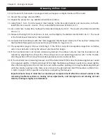
10. At the end of 16 seconds an average velocity will appear on digital readout of the meter.
11. Record the average velocity (FPM).
12.
Repeat the process for any additional Ventilator sections.
13.
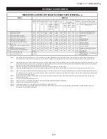
Using Table T-5-4-1, find the nearest Inlet Velocity to the Recorded Velocity and read across to the Re
-
lated CFM Per Lineal Ft. column. This is called the Determined CFM Per Lin. Ft.
14.
As an alternate to step #13, multiply the Recorded Velocity by 0.217. The result is the Determined CFM
Per Lin. Ft.
15.
Measure the length of the Ventilator, in feet, and multiply by the Determined CFM Per Lin. Ft. The result
is the Total Exhaust Volume for the Ventilator.
16.
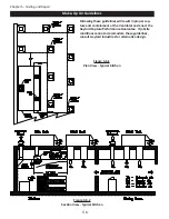
Compare this Total Exhaust with the “Min. Suggested Total Exhaust Volume For This Section” stamped on
the Ventilator Nameplate and proceed to step 17 (Refer to Figure 5-4-1).
17.
The acceptable range is 0% low to 10% high. If the CFM is not within acceptable range then corrective
action must be taken to bring the exhaust volume within design.
18.
If the Ventilator does not include a Balancing Damper, the exhaust volume must be increased or de
-
creased by adjusting the exhaust fan. If the exhaust fan is not operating properly, refer to the Trouble
-
shooting section of this manual for possible problems and corrective action.
19.
If the Ventilator has a balancing damper, and if the Determined CFM is low, the Balancing Damper needs
to be opened slightly. If the Determined CFM is high the Balancing Damper needs to be closed slightly.
Place the Sensing Head at the Air Inlet Slot and continue either opening or closing the Balancing Damper
until the velocity reading on the meter is at or close to the desired Inlet Slot FPM number on Table T-5-4-
1. Refer to page 2-19 for specific instructions
on adjusting the dampers.
Important Note: Keep in mind that as one damper is adjusted it will affect the exhaust volume in the
remaining Ventilator sections so making minor adjustments, and coming back and retaking Air Inlet
Velocity readings is highly recommended.
Summary of Contents for ELXC Series
Page 40: ...4 6 INTENTIONALLY LEFT BLANK ...
Page 74: ...7 1 Chapter 7 Wiring Diagrams ELXC GBD with AUTOSTART ...
Page 75: ...7 2 Chapter 7 Wiring Diagrams ELXC GFBD with AUTOSTART ...
Page 76: ...7 3 Chapter 7 Wiring Diagrams ELXC GBD UVi with AUTOSTART ...
Page 77: ...7 4 Chapter 7 Wiring Diagrams ELXC GFBD UVi with AUTOSTART ...
Page 83: ...A 6 INTENTIONALLY LEFT BLANK ...


