5-5
Chapter 5 - Testing and Repair
Measuring Airflow - Cont.
Capture Performance
All Gaylord Ventilators are factory engineered to operate at a specific exhaust volume, CFM (Cubic Feet per Min
-
ute), based on, primarily, the type of cooking appliance, and the exact model of the Ventilator. Capture perfor
-
mance is based on two primary functions, 1) the ventilator is exhausting the engineered CFM and 2) the make-up
air is being introduced correctly. Make-up air introduced incorrectly will typically result in smoke and heat loss
into the kitchen, even if the Ventilator is operating at the engineered CFM. Make-up air is typically brought into
the kitchen space through ceiling diffusers or through a combination of Gaylord Make-Up Air Plenum Boxes,
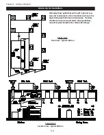
Model PBW, (refer to Figure 5-6-1) and ceiling diffusers.
Capture and Performance Guarantee
Gaylord Industries provides the following guarantee for all Gaylord Ventilators:
Gaylord Capture Performance Guarantee
Gaylord Industries warrants the Capture Performance of the Ventilator, only if the Exhaust Air Volumes are cor
-
rect, per the Exhaust Volume Guidelines as stated below, and the Make-up Air Volumes are correct and delivered
correctly per the Make-up Air Delivery Guidelines as stated below.
Exhaust Volume Guidelines
1.
The amount of exhaust CFM through the Ventilator shall be between 100% and 110% of the values stamped
on the Ventilator Nameplate for each Ventilator section.
Make-up Air Delivery Guidelines
A. With Gaylord Plenum Boxes and ceiling diffusers.
1. Gaylord Plenum Boxes Model PBW, shall be located immediately in front of the Ventilator, a
minimum of 18” from the lower lip of the Ventilator to the discharge surface of the Plenum Box.
(Refer to Figures 5-6-1 and 5-6-2).
2. The amount of make-up air delivered through the Gaylord Plenum Box(s) shall be between 90%
and 100% of the values shown on Gaylord Submittal Drawings.
3. The amount of make-up air through the Plenum Boxes shall not exceed 60% of the exhaust vol-
ume of the Ventilator.
4. Ceiling diffusers shall be at least 6’-0” away from all sides of the Ventilator and the outlet velocity
at the diffusers shall not exceed 150 Feet per Minute (FPM).
B. With ceiling diffusers only.
1. Ceiling diffusers shall be at least 15’-0” away from all sides of the Ventilator and the outlet
velocity at the diffusers shall not exceed 300 Feet per Minute (FPM) (Refer to Figure 5-6-1).
C. Additional Requirements.
1. The maximum velocity of the make-up air from diffusers, transfer air diffusers, or any other type
of diffusers shall not be greater than 75 FPM on all open sides of the lower edge of the Ventilator.
2. Cross drafts from pass through windows, hallways, or other openings shall not exceed 50 FPM.
3. All forms of make-up air, such as ceiling diffusers, transfer air diffusers, and Plenum Boxes
must
be evenly distributed around each Ventilator to prevent unequal pressurization.
4. Kitchen pressurization shall not exceed -0.02” W.G. relative to the dining or adjacent spaces as
stated in NFPA-96 and ASHRAE Standard 154.
5. For more information on acceptable methods of make-up air delivery reference ASHRAE
Standard 154.
Summary of Contents for ELXC Series
Page 40: ...4 6 INTENTIONALLY LEFT BLANK ...
Page 74: ...7 1 Chapter 7 Wiring Diagrams ELXC GBD with AUTOSTART ...
Page 75: ...7 2 Chapter 7 Wiring Diagrams ELXC GFBD with AUTOSTART ...
Page 76: ...7 3 Chapter 7 Wiring Diagrams ELXC GBD UVi with AUTOSTART ...
Page 77: ...7 4 Chapter 7 Wiring Diagrams ELXC GFBD UVi with AUTOSTART ...
Page 83: ...A 6 INTENTIONALLY LEFT BLANK ...

