5-8
Chapter 5 - Testing and Repair
Replacing UV Lamps - Cont.
Instructions for Replacing UV Lamps
To replace UV lamps carefully use the following step by step instructions.
1.
Turn off all power to the Gaylord Command Center.
2.
Turn off all circuits that supply power to the UV Lamps.
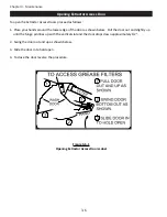
3. Open the UV Module Access Door (Refer to Figure 5-9-1).
4.
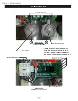
Disconnect the Lamp / Ballast Connector cable by twisting the connector counter clockwise (refer to Figure
5-13-1).
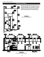
5. Carefully slide out the UV Module (refer to Figure 5-9-1).
6.
Referring to Figure 5-9-2, remove the two bolts pc #9, washer’s pc #8, Module End Cap pc #7, and Silicon
Gasket pc #6 from each end of the module.
7.
Slide off each UV Lamp Sockets, pc #5, from the Lamps at each end of the Module.
•
Each UV Lamp Socket should be labeled 1 to 6.
•
Lamp #1 is at the front of the Ventilator when the UV Module is installed.
•
Lamp #6 is at the back of the Ventilator when the UV Module is installed.
•
Be sure to re-label the Lamp Sockets if necessary.
8.
Lubricate the Lamps around the Grommets, pc # 2, on each end of the UV Lamp with a small amount of
Formula G-510EF or similar detergent.
9. CAREFULLY slide the UV Lamp out one end.
10. Inspect the Grommets around the Lamps.
•
Replace any Grommet that show cracks, or any other damage.
11.
Check all UV Lamp Sockets and wires for damage.
•
Replace Light Sockets if the socket or wire show damage.
12. Before installing, lubricate each of the new UV Lamps with a small amount of Formula G-510EF or similar
detergent.
13. Slide in all the new UV Lamps.
14.
Reconnect all the UV Lamp Sockets to the appropriate numbered Lamp, #1 through #6.
15.
Check the Silicon Gaskets for cracks or deterioration. Replace if needed.
16.
Re-install the Silicon Gaskets, Module End Caps, Washers and bolts, and torque the bolts to 20 in – lbs.
17.
Slide the UV Module back into the Ventilator.
18. Reconnect the Lamp / Ballast Connector Cable.
19.
Check the UV Module Access Door Gasket for cracks or deterioration. Replace if needed.
20. Close the UV Module Access Door.
21. Close all Extractor Access Doors.
22. Turn on all circuits that supply power to the UV Lamps.
23. Turn on power to the Gaylord Command Center.
24.
Check for proper operation of the UV Lamps and Pressure Switches following the Test Lamps and Ballasts
instructions on page 3-3.
Summary of Contents for ELXC Series
Page 40: ...4 6 INTENTIONALLY LEFT BLANK ...
Page 74: ...7 1 Chapter 7 Wiring Diagrams ELXC GBD with AUTOSTART ...
Page 75: ...7 2 Chapter 7 Wiring Diagrams ELXC GFBD with AUTOSTART ...
Page 76: ...7 3 Chapter 7 Wiring Diagrams ELXC GBD UVi with AUTOSTART ...
Page 77: ...7 4 Chapter 7 Wiring Diagrams ELXC GFBD UVi with AUTOSTART ...
Page 83: ...A 6 INTENTIONALLY LEFT BLANK ...

