5-11
Chapter 5 - Testing and Repair
Replacing UV Lamp Sockets - Cont.
Instructions for Replacing UV Lamp Sockets – Individual Method – Cont.
11.
Slide off the UL Lamp Sockets from the Lamp and remove the UV Lamp Socket Short Wire. CAUTION:
Do not pull the UV Lamp Long Wire at this time. It is needed to pull the new Lamp Socket through the
conduit.
12. Using a Pin Removal Tool, Gaylord Part Number 20415, push the associated pin out of the base of the
Pined Receptacle.
13.
All Lamp Sockets come with a 76” wire length so each has to be cut to match the one being replaced.
14.
Cut the correct length wire, and at the end opposite the Lamp Socket, strip back 1/4” of the insulation.
Solder on the pin that is provided.
15.
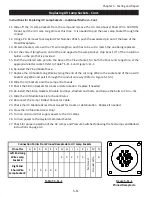
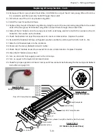
Push the soldered wire pin into the base of the Pined Socket, for both the Short and Long Wire, at the
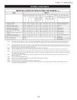
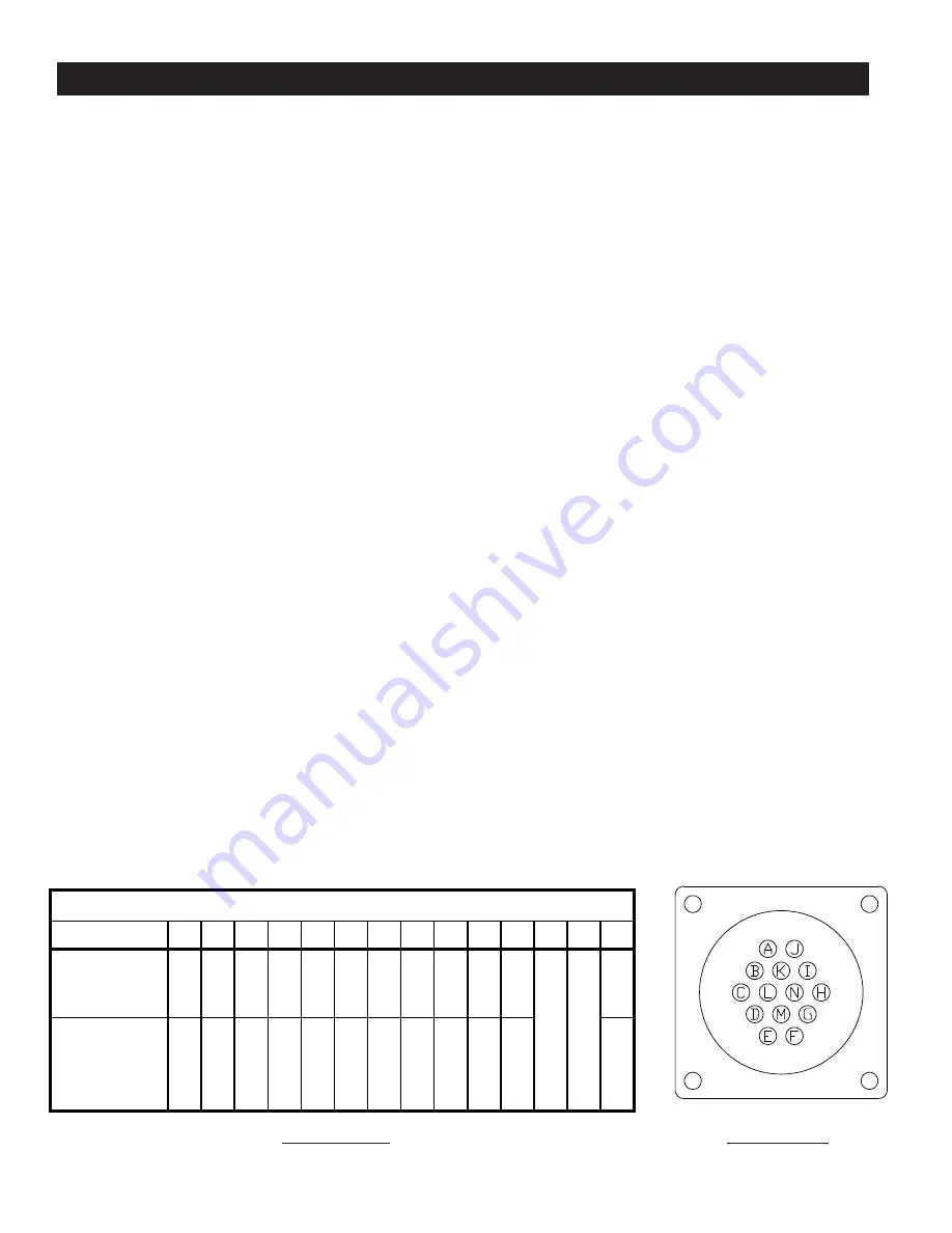
appropriate letter socket. Refer to Table T-5-11-1 and Figure 5-11-1.
16.
Re-install the Pined Socket base.
17.
Replace the UV Socket Long Wire by tying the end of the cut Long Wire to the socket end of the new UV
Socket Long Wire and pull it through the conduit wire way (Refer to Figure 5-13-3).
18.
Slide the UV Sockets onto the Lamp at both ends.
19.
Check the Silicon Gaskets for cracks or deterioration. Replace if needed.
20.
Re-install the Silicon Gaskets, Module End Caps, Washers and bolts, and torque the bolts to 20 in – lbs.
21.
Slide the UV Module back into the Ventilator.
22. Reconnect the Lamp / Ballast Connector Cable.
23.
Check the UV Module Access Door Gasket for cracks or deterioration. Replace if needed.
24. Close the UV Module Access Door.
25. Turn on all circuits that supply power to the UV Lamps.
26. Turn on power to the Gaylord Command Center.
27.
Check for proper operation of the UV Lamps and Pressure Switches following the Test Lamps and Ballasts
instructions on page 3-3.
Table T-5-11-1
Figure 5-11-1
Pinned Receptacle
Pin
Letter
Left
End
Long
Wire
Lamp
Sock
Ri
gh
t
En
d
Sh
A
1
B
2
C
3
D
4
E
5
F
6
G
4
H
3
I
2
J
1
K
5
L
M
N
6
Pin Letter
A
B
C
D
E
F
G
H
I
J
K
L
M
N
Left End Long
Wire Lamp
Socket #
4
3
2
1
5
6
Right End
Short Wire
Lamp Socket #
1
2
3
4
5
6
Table T-5-18-1
N
ot
Use
d
G
ro
und
W
ir
e
Connection Points From Pinned Receptacle to UV Lamp Sockets
Table T-5-18-1
Alternate
Connection
Points From
Pinned
Receptacle to UV
Ground Wire
Not Used
Summary of Contents for ELXC Series
Page 40: ...4 6 INTENTIONALLY LEFT BLANK ...
Page 74: ...7 1 Chapter 7 Wiring Diagrams ELXC GBD with AUTOSTART ...
Page 75: ...7 2 Chapter 7 Wiring Diagrams ELXC GFBD with AUTOSTART ...
Page 76: ...7 3 Chapter 7 Wiring Diagrams ELXC GBD UVi with AUTOSTART ...
Page 77: ...7 4 Chapter 7 Wiring Diagrams ELXC GFBD UVi with AUTOSTART ...
Page 83: ...A 6 INTENTIONALLY LEFT BLANK ...


