5-15
Chapter 5 - Testing and Repair
UV Ballast Box - Cont.
Replacing Ballast Boards
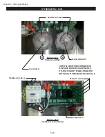
To replace the Ballast Board proceed as follows (refer to Figure 5-20-2 and 5-22-1):
Caution: Turn off all power to the Command Center and to the UV Ballast Box. There is a risk of shock,
injury, and /or death from contact with live electrical components.
1.
Turn off all power to the Gaylord Command Center.
2.
Turn off all circuits that supply power to the UV Lamps.
3. Remove the UV Ballast Box Access Cover.
4. Unplug the Ballast Board power.
5. Remove the two screws that hold the Front Ballast Board Plate. Remove the Rear Ballast Board Plate if
necessary.
6.
Remove all wires from the terminal blocks. Label if necessary.
7.
In three corners of the Ballast Board are plastic standoff retainers and the fourth corner is a screw. Us
-
ing a screwdriver push in the retainer tab on the plastic standoff while pulling up on the Ballast Board.
Remove the one screw.
8.
Install a new Ballast Board, wire the plug in harness to the terminal block, mount the Ballast Board to the
Ballast Board Plate and remount, and plug the harness back in.
9.
Inspect the UV Ballast Box Access Cover Gasket for cracks and deterioration and replace if necessary.
10. Replace the Access Cover.
11. Turn on all circuits that supply power to the UV Lamps.
12. Turn on power to the Gaylord Command Center.
13.
Check to make sure both Green lights are on.
Replacing UV Ventilation Control Board
The UV Ventilation Control Board (Refer to Figures 5-19-2 and 5-22-2) monitors all the Safety Interlock Pres
-
sure Switches. If the Safety Interlock Pressure Switches are in a normal operational condition, a signal is sent
to activate the Ballast Contactor allowing the UV System to operate. If a Safety Interlock Pressure Switch
detects a problem, such as an Extractor Access Door or UV Module Access Panel being left open, a signal is
sent to deactivate the Ballast Contactor which turns off the UV System. The UV Ventilation Control Board has
three main components, the UV Monitoring Board, the Ballast Contactor and the Status Light Relay. If it is
determined that any of these three components are defective replace as follows:
Caution: Turn off all power to the Command Center and to the UV Ballast Box. There is a risk of shock,
injury, and /or death from live electrical components.
1.
Turn off all power to the Gaylord Command Center.
2.
Turn off all circuits that supply power to the UV Lamps.
3. Remove the UV Ballast Box Access Cover.
4.
Uncouple the wire plug that interties the UV Ventilation Control Board to the Ballast Boards.
5. Unplug the wires leading to the Pressure Switches.
6.
Remove all wires from the appropriate terminal blocks. Label if necessary.
Summary of Contents for ELXC Series
Page 40: ...4 6 INTENTIONALLY LEFT BLANK ...
Page 74: ...7 1 Chapter 7 Wiring Diagrams ELXC GBD with AUTOSTART ...
Page 75: ...7 2 Chapter 7 Wiring Diagrams ELXC GFBD with AUTOSTART ...
Page 76: ...7 3 Chapter 7 Wiring Diagrams ELXC GBD UVi with AUTOSTART ...
Page 77: ...7 4 Chapter 7 Wiring Diagrams ELXC GFBD UVi with AUTOSTART ...
Page 83: ...A 6 INTENTIONALLY LEFT BLANK ...


