5-16
Chapter 5 - Testing and Repair
UV Ballast Box - Cont.
Replacing UV Ventilation Control Board – Cont.
7.
Remove the 2 screws that hold the Din Rail and remove the entire assembly.
8.
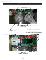
Loosen and slide off the end retainer (Refer to Figure 5-19-2).
9.
Slide off the components as required.
10.
Slide on the new component and tighten the end retainer.
11. Reinstall the Din Rail and reconnect all the wires.
12.
Inspect the UV Ballast Box Access Box Access Cover Gasket for cracks and deterioration and replace if
necessary.
13. Replace the Access Cover.
14. Turn on all circuits that supply power to the UV Lamps.
15. Turn on power to the Gaylord Command Center.
Replacing Ventilation Fan
The Ventilation Fan removes the heat generated by all the electrical components. It is on, typically, when
-
ever the exhaust fan is on. If the Ventilation Fan is not pushing enough air, pull out the mesh filter, clean
and replace. If the Ventilation Fan is determined to be defective, replace it as follows (Refer to Figure
5-20-2).
Caution: Turn off all power to the Command Center and to the UV Ballast Box. There is a risk of shock,
injury, and /or death from live electrical components.
1.
Turn off all power to the Gaylord Command Center.
2.
Turn off all circuits that supply power to the UV Lamps.
3. Remove the UV Ballast Box Access Cover.
4.
Disconnect the wires from the terminal block.
5.
Remove the 4 screws from the holding bracket and remove the fan.
6. Install a new fan in the reverse order.
7.
Inspect the UV Ballast Box Access Box Access Cover Gasket for cracks and deterioration and replace if
necessary.
8. Replace Access Cover.
9. Turn on all circuits that supply power to the UV Lamps.
10. Turn on power to the Gaylord Command Center
Pressure Switches
There are two Pressure Switches used as the Safety Interlocks that monitor if all the XGS Extractors are in
place, and if the UV Module Access Panels are closed and latched. If one or more XGS Extractors are missing
and / or one or more UV Module Access Panels are not in place the Pressure Switches will sense a pressure
drop and shut down the UV System.
A 1/8“copper tube runs from a Static Pressure Tap in the Ventilator plenum into the Ballast Box. The copper
tube is then connected to a clear vinyl tube which in turn is connected to the Pressure Switch. The vinyl tube
is called a Vacuum Release Tube and has a small hole mid way in the tube to allow trapped pressure that may
Summary of Contents for ELXC Series
Page 40: ...4 6 INTENTIONALLY LEFT BLANK ...
Page 74: ...7 1 Chapter 7 Wiring Diagrams ELXC GBD with AUTOSTART ...
Page 75: ...7 2 Chapter 7 Wiring Diagrams ELXC GFBD with AUTOSTART ...
Page 76: ...7 3 Chapter 7 Wiring Diagrams ELXC GBD UVi with AUTOSTART ...
Page 77: ...7 4 Chapter 7 Wiring Diagrams ELXC GFBD UVi with AUTOSTART ...
Page 83: ...A 6 INTENTIONALLY LEFT BLANK ...

