A-2
Appendix A, Page A-2
Installation Requirements - cont.
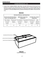
7. Caution: When installing Ventilators incorporating a UV system, ELXC-UVi Series, do not cover the UV
Ballast Box, mounted on top of the Ventilator, with building insulation. Covering the Ballast Box inlet
and outlet ventilation openings will cause the box to overheat which could result in failure of electrical
components. Covering the Ballast Box with insulation will damage the Ventilator and void the War-
ranty.
Table T-A-2-1
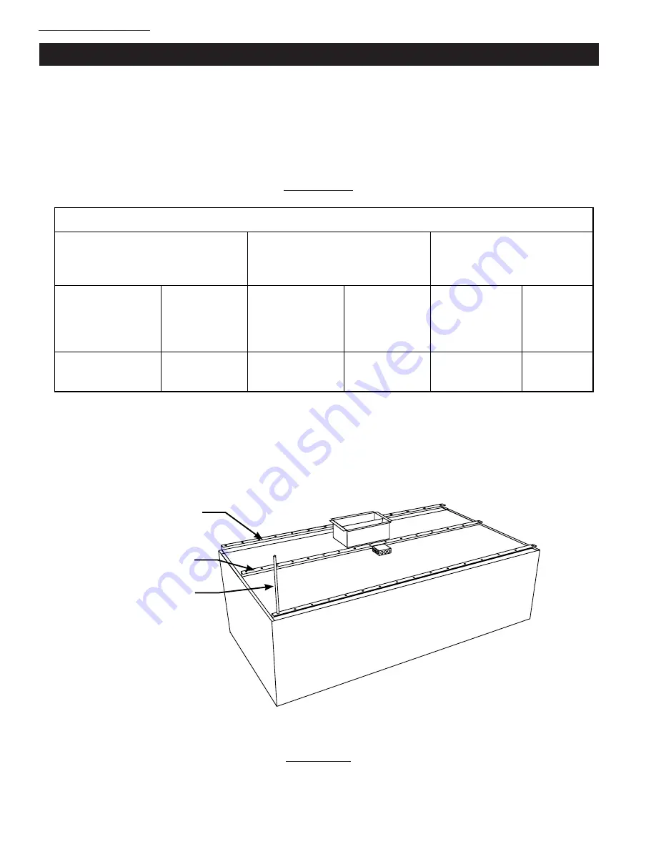
Figure A-2-1
Ventilator Hanging Points
REAR MOUNTING BRACKET
MIDDLE MOUNTING BRACKET
FRONT MOUNTING BRACKET
Appendix A, Page A-2
INSTALLATION REQUIREMENTS
7.
Caution: When installing Ventilators incorporating a UV system, ELXC-UVi Series, do not cover
the UV Ballast Box, mounted on top of the Ventilator, with building insulation. Covering the
Ballast Box inlet and outlet ventilation openings will cause the box to overheat which could
result in failure of electrical components. Covering the Ballast Box with insulation will void the
Ventilator and the Warranty.
Table T-A-2-1
Recommend Minimum Mounting Devices
Rear Mounting Bracket, Bolting
to Wall or Hanging With Rods
Middle Mounting Bracket
Hanging Rods
Front Mounting Bracket
Hanging Rods
Max. Distance
From End of
Ventilator
Section
Max. Spacing
Between
Supports
Max. Distance
From End of
Ventilator
Section
Max. Spacing
Between
Supports
Max. Distance
From End of
Ventilator
Section
Max.
Spacing
Between
Supports
12"
72"
36"
72"
12"
72"
Figure A-2-1
Ventilator Hanging Points
Summary of Contents for ELXC Series
Page 40: ...4 6 INTENTIONALLY LEFT BLANK ...
Page 74: ...7 1 Chapter 7 Wiring Diagrams ELXC GBD with AUTOSTART ...
Page 75: ...7 2 Chapter 7 Wiring Diagrams ELXC GFBD with AUTOSTART ...
Page 76: ...7 3 Chapter 7 Wiring Diagrams ELXC GBD UVi with AUTOSTART ...
Page 77: ...7 4 Chapter 7 Wiring Diagrams ELXC GFBD UVi with AUTOSTART ...
Page 83: ...A 6 INTENTIONALLY LEFT BLANK ...

