B-3
Appendix B, Page B-3
Ventilator Start-Up Inspection And Tests - cont.
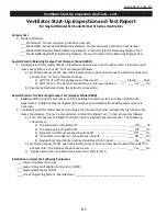
VENTILATOR START-UP INSPECTION AND TES
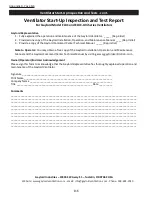
Ventilator Start-Up Inspection and Test Report
For Gaylord Model ELXC and ELXC-UVi Series Ventilators
Facility Name
__________________________________
Gaylord Representative Company Name
Address
_______________________________________ __________________________________________
City
_______________________
State
_____
Zip
______
Gaylord Rep Name
__________________________
Facility Contact Name
___________________________
Signature
_________________________________
Facility Contact Phone #
__________________________
Date of Start-Up
____________________________
Facility E-Mail
___________________________________
Gaylord File Number
________________________
Exhaust Volume Readings
1.
Push the START FAN button on the Gaylord Command Center. The exhaust fan should come on. Note;
if the Ventilator includes an electric damper it may take up to 45 seconds for the exhaust to come up
to 100%. Did the exhaust fan come on. ………………………………………………………………………. _____ Yes ____
No
2.
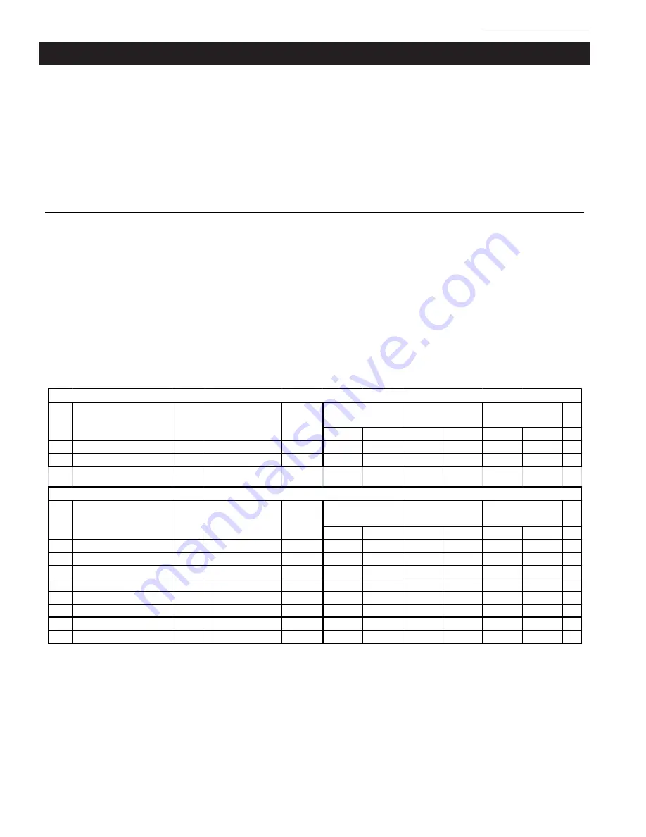
Determine the exhaust volume for each Ventilator section by either the Static Pressure Method or the
Velocity Method as detailed in the ELXC Series Operation, Maintenance and Installation Manual.
Record all readings in the chart below. Record the Design CFM from the Gaylord Drawings or the
Ventilator Nameplate. If the installation includes a Plenum Box make up air system, take velocity
readings and record on the chart.
Make-Up Air
1.
When the Exhaust Fan is on the Make-Up Air should be on. Is the Make-Up air on. … ____ Yes ____ No
2.
Type of Make-Up Air discharge.
___ Ceiling Registers located approximately ____ ft. in front of Ventilator.
___ Ceiling Plenum Box located immediately in front of Ventilator. Dimension from bottom of
Ventilator to discharge screen of Plenum Box. ______
___ Ceiling Plenum Box located approximately ____ ft. in front of Ventilator.
___ Linear Diffusers or registers located approximately ____ ft. in front of Ventilator.
___ Other ____________________________________________________________
% +
or -
Design
Actual
Design
Actual
Design
Actual
K-112 Griddle Fryer Line
10'-0"
125
664
610
1440
1325
-8%
K-114 Oven Kettle Line
16'-0"
110
0.22
0.28
2512
3039
21%
% +
or -
Design
Actual
Design
Actual
Design
Actual
Item
No.
Inlet Velocity
Plenum
Box FPM
Plenum
Box FPM
Total CFM
Total CFM
Exhaust Volume Test Chart - Example
Length
Exhaust Volume Test Chart
Item
No.
Ventilator Description Length Ventilator Serial #
Plenum Static
Inlet Velocity
Plenum Static
Ventilator Serial #
Ventilator Description
Summary of Contents for ELXC Series
Page 40: ...4 6 INTENTIONALLY LEFT BLANK ...
Page 74: ...7 1 Chapter 7 Wiring Diagrams ELXC GBD with AUTOSTART ...
Page 75: ...7 2 Chapter 7 Wiring Diagrams ELXC GFBD with AUTOSTART ...
Page 76: ...7 3 Chapter 7 Wiring Diagrams ELXC GBD UVi with AUTOSTART ...
Page 77: ...7 4 Chapter 7 Wiring Diagrams ELXC GFBD UVi with AUTOSTART ...
Page 83: ...A 6 INTENTIONALLY LEFT BLANK ...

