background image


MIUM0001_REV01_ RKB_20140130 MIUM ENG.docx 

11 


Air duct connections 


The ducts must be the correct dimension based on the functions of system and the air diffusion characteristics 
of the unit fans. 


To  prevent  the  formation  of  condensation  and  cut  down  the  sound  level  it  is  advised  to  use  internally  lined 
ducts. 


To avoid the transmission of unit vibrations into the environment, it is advised to fit an antivibrating joint between 
the  fans  and ducts.  The  electrical  continuity  must be  guaranteed  between the  ducts  and  the  apparatus  via  an 
earth cable. 


Water connections 

 
The installation and connecting of the piping is an operation that must be done correctly, otherwise it may compromise 
the performance of the system. At worst it may cause irreversible damage to the machine. These operations are to be 
effectuated by 

qualified personnel.


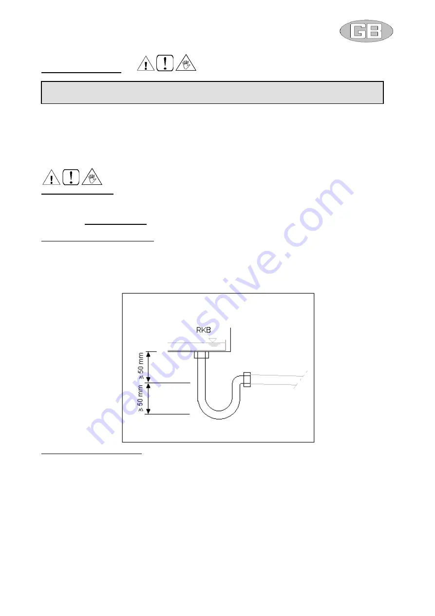
Condensation outlet connection 


The system of drainage must provide an adequate trap able to allow the condensation run off on under pressure 
conditions. 


The trap must be designed as shown on the following 

figure


The trap must have a tap for correct cleaning of the lower part, and must allow an easy disassembly. 


The path of the condensation drainage tube must always have a gradient toward external. 


Insure that the condensation run-off tube does not interfere with discharge of the unit. 


Water coil connection (SAF) 


The water heating or cooling coil (

SAF) is supplied with GAS “male” threaded headers. 


The tightening must be carried out with extreme care to avoid damage to the copper collectors of the coil. 


The path of the tubes must be studied in a way to avoid obstacles should it be necessary to extract the unit coil. 


Inlet and outlet water must consent the thermal exchange against the current. Follow instructions found on the 
WATER INLET and WATER OUTLET plate. 


Provide an air valve at the top of the unit, and a water discharge valve at the bottom. 


Reinforce sufficiently the units external tubes to avoid offloading the weight onto the coil. 


Once connection has been effectuated, fix the external seal flush against the control panel, in this way avoiding 
the passing of air. 


The insulation must not rest against the paneling, as this may provoke burning. 


For  control  purposes,  organize  the  interception  of  the  tube  side  coil  when  the  fan  is  off,  to  avoid  internal 
overheating and possible damage to internal components. 


Provide an anti-freeze system. 


Provide a cut out switch to isolate the coil from the rest of the circuit in case of extensive maintenance needs. 


Should the unit be installed in particularly cold areas, drain completely before plant shut-off long periods. 

IMPORTANT:  IT  IS  IMPORTANT  NOT  TO  PLACE  IN  OPERATION  THE  UNIT  IF  THE  FAN  OUTLETS  ARE 
NOT DUCTED OR NOT PROTECTED BY A SAFETY NET ACCORDING TO THE ACTAUL REGULATION. 

Summary of Contents for RKB 1000

Page 1: ...1_ RKB_20140130 MIUM ENG docx 1 I IN NS ST TA AL LL LA AT TI IO ON N O OP PE ER RA AT TI IO ON N A AN ND D M MA AI IN NT TE EN NA AN NC CE E M MA AN NU UA AL L 50 EFFICIENCY AIR TO AIR HEAT RECOVERY UNIT SERIES RKB ...

Page 2: ...ctive 2004 108 CE and Ecodesign Directive 2009 125 CE The unit belonging to the above series is designed according to the following main safety prescriptions principals of safety integration used materials free from risk safety while transportation handling and installation protection against mechanical risks protection against electrical risks protection against fire risks design and construction...

Page 3: ...C SHOCK ATTENTION AUTHORIZED PERSONNEL ONLY 1 INTRODUCTION pag 4 2 DIMENSIONS AND WEIGHTS pag 5 3 INSTALLATION CONFIGURATIONS pag 6 4 TRANSPORTATION pag 7 5 INSTALLATION CONNECTION pag 8 6 WIRING DIAGRAMS pag 10 7 STANDARD MAINTENANCE pag 11 8 TROUBLESHOOTING pag 12 9 MATERIAL DISPOSAL pag 12 ...

Page 4: ...cordance with the laws in force in the country in which the unit is installed Unauthorized tampering with the electrical and mechanical equipment will VOID THE WARRANTY Check the electrical specifications on the identification plate before making the electrical connections Read the instructions in the specific section where the electrical connections are described If the unit must be repaired for ...

Page 5: ...f the horizontal series RKB M Supply E Exhaust R Return A Fresh air RKB 500 1000 2000 3000 4000 A mm 750 900 1000 1300 1400 B mm 750 900 1000 1300 1400 C mm 290 410 470 530 705 D Ø mm 200 315 355 450 500 E mm 145 205 235 265 352 F mm 202 240 265 340 365 Ø condensate mm 2 x 1 2 F 2 x 1 2 F 2 x 1 2 F 2 x 1 2 F 2 x 1 2 F Weight kg 41 68 99 155 235 E90 R90 A90 E M A R M90 ...

Page 6: ...ive the following combinations each of them is a specific unit orientation to be specified when ordering Horizontal configuration RKB Configurations shown on the figure below are possible A fresh air R return air M supply air E exhaust air TYPE A Configurations shown on the figure below are possible A fresh air R return air M supply air E exhaust air TYPE B M90 E A M R E90 R90 A90 M R E A A90 R90 ...

Page 7: ...ch inlet outlet panels for example from E to E90 you may need to exchange two panels between each other Vertical configuration RKB vertical kit Configurations shown on the figure below are possible A fresh air R return air M supply air E exhaust air TYPE A TYPE B To modify the position of the suction inlets it is sufficient to exchange two panels each other A R E M M90 M90 A R E M E90 E90 ...

Page 8: ... the unit electric and hydraulic connections and any air pipes ducts or free passages Neglecting these aspects may decrease performance and operational life of the unit and therefore increase the operating costs and maintenance Units are designed to be installed INSIDE or PARTIALLY OUTSIDE roof cover needed and in fixed positions Before placing the unit be sure that the location is in a safe acces...

Page 9: ...cers of such products Before placing in function the unit check the perfect connection of the various components and the internal parts of the system Avoid at all costs human contact with moving parts and contact with the parts themselves Do not commence with servicing or cleaning of the unit before the unit has been disconnected from the main supply The maintenance and the substitution of damaged...

Page 10: ... of free space as indicated in the following figure This permits ease of installation and maintenance Machine positioning The unit is equipped with anti vibration support plates Referring to the following figure the following are instructions to fix the unit to its supports 1 Carry out the drilling of the ceiling and fit the four M8 threaded bolts 1 2 Position the unit on the four bolts using the ...

Page 11: ...not interfere with discharge of the unit Water coil connection SAF The water heating or cooling coil SAF is supplied with GAS male threaded headers The tightening must be carried out with extreme care to avoid damage to the copper collectors of the coil The path of the tubes must be studied in a way to avoid obstacles should it be necessary to extract the unit coil Inlet and outlet water must cons...

Page 12: ...ied and authorized personnel according to EU Regulation 303 2008 of 2 April 2008 and later that requires companies and technicians that perform maintenance repair leakage checking and recovery recycling gases must be certified as required by local regulations Comply with the safety precautions given in the relative section of this manual and take all the necessary precautions The following informa...

Page 13: ...ned 8 TROUBLESHOOTING Failure searching and problem solving schedule Founded failure Probable cause Possible solution Fans are not running Power supply is switched off Wrong or loose electrical connections Motors on thermal protection mode Switch on the power supply Restore the right connections Check motor current Air performance decreasing Air filter dirty Air duct blocked Clean or replace filte...

Reviews: