GBC AdvancedPunch Pro
08/20/2015
Repairs/Adjustments
4-27
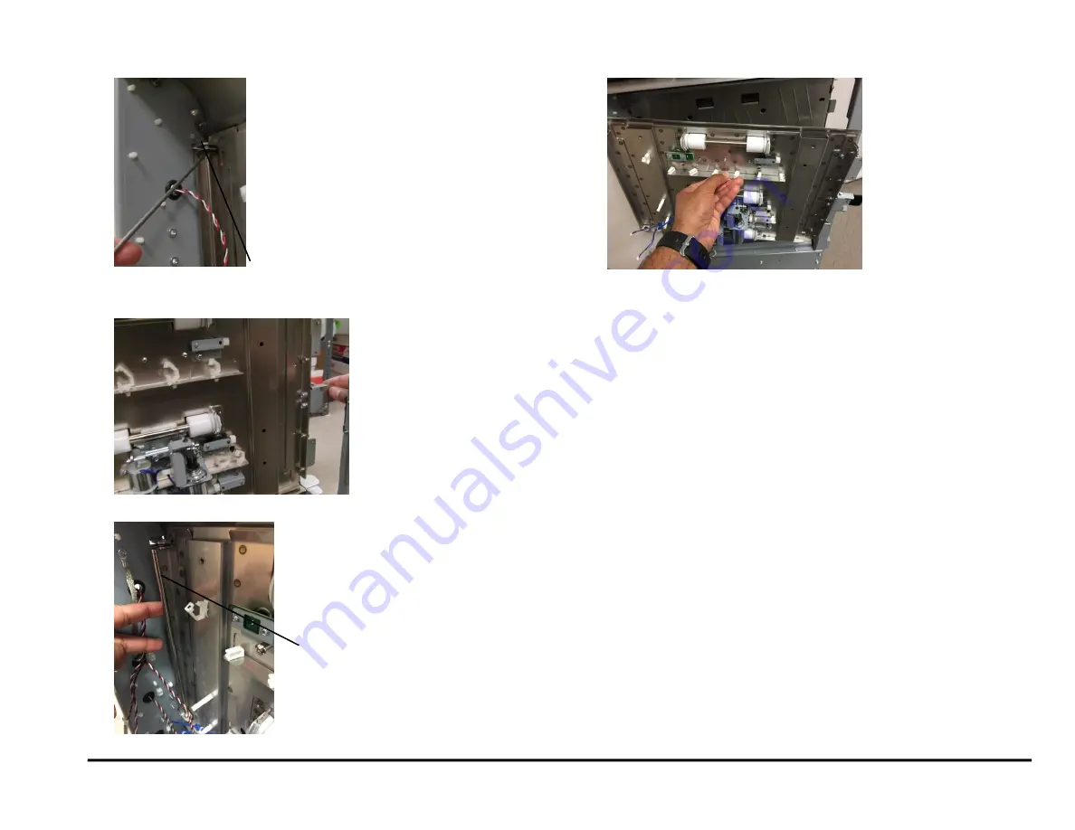
12. Remove the E-Ring from the top of the Idler Panel Shaft.
13. Open the Entrance Idler Panel from the front side.
14. Carefully remove the Shaft.
(Cont.)
15. Grasp the Entrance Idler Panel and remove it.
16. Do the following to transfer the Sensors, Solenoid Modules, Idler
Rollers, Springs, and Panel Magents to the new weldment.
REP 2.12
Idler Roller replacement
Paper path sensor (S2, S3, S4) Replacement
Disengaging Roller Solenoid Replacement
Installation Procedure
1. Place the Entrance Idler Panel in position.
2. Insert the Shaft through the holes (2) at the left side of the Entrance
Idler Panel.
3. Install the E-Rings (2) at the top and bottom of the Shaft.
4. Connect the Connectors for Solenoids SOL3 & SOL4 to the header.
5. Connect the Connectors for Sensors S2, S3, S4 and S1b.
6. Place the sensor cables into the Cable Clamps, and close the
Clamps.
7. Install the Ground strap.
8. Do ADJ 1.7 Idler Panel Magnetic Latches Adjustment.
9. Do REP 1.18 to install the Docking Bracket.
10. Do REP 1.8
to install the Side Cover.
11. Do GP 6.3
Dock the Punch
to connect the Punch to the upstream
and downstream devices.
12. Close the Front Door.
13. Connect the Power Cord.
14. Power ON the entire printing system.
E-Ring
Shaft
Summary of Contents for AdvancedPunch Pro
Page 26: ...Service Call Procedures 08 20 2015 GBC AdvancedPunch Pro 1 8 Notes ...
Page 28: ...GBC AdvancedPunch Pro 11 07 2018 RAPS 2 2 ...
Page 78: ...Punch Quality 11 07 2018 GBC AdvancedPunch Pro 3 2 This page intentionally left blank ...
Page 230: ...Repairs Adjustments 08 20 2015 GBC AdvancedPunch Pro 4 142 Notes ...
Page 263: ...GBC AdvancedPunch Pro 09 11 2018 Parts List 5 33 PL 6 4 Wiring Drawing OEM Configurations ...
Page 264: ...Parts List 09 11 2018 GBC AdvancedPunch Pro 5 34 PL 6 5 Wiring Drawing DFA Configurations ...
Page 360: ...General Procedures and Information 09 11 2018 GBC AdvancedPunch Pro 6 90 Notes ...
Page 362: ...Wiring Data 08 20 2015 GBC AdvancedPunch Pro 7 2 This page intentionally left blank ...
Page 363: ...GBC AdvancedPunch Pro 08 20 2015 Wiring Data 7 3 System Wiring ...
Page 364: ...Wiring Data 08 20 2015 GBC AdvancedPunch Pro 7 4 System Wiring DFA Configurations ...
Page 365: ...GBC AdvancedPunch Pro 08 20 2015 Wiring Data 7 5 Plug Jack Connectors ...
Page 366: ...Wiring Data 08 20 2015 GBC AdvancedPunch Pro 7 6 Plug Jack Connectors DFA Configurations ...
Page 367: ...GBC AdvancedPunch Pro 08 20 2015 Wiring Data 7 7 Notes ...
Page 368: ...GBC AdvancedPunch Pro 08 20 2015 Installation Instructions 8 1 8 Installation Instructions ...
Page 369: ...Installation Instructions 08 20 2015 GBC AdvancedPunch Pro 8 2 ...
Page 370: ...GBC AdvancedPunch Pro 08 20 2015 Installation Instructions 8 3 ...
Page 371: ...Installation Instructions 08 20 2015 GBC AdvancedPunch Pro 8 4 ...
Page 372: ...GBC AdvancedPunch Pro 08 20 2015 Installation Instructions 8 5 ...
Page 373: ...Installation Instructions 08 20 2015 GBC AdvancedPunch Pro 8 6 ...
Page 374: ...GBC AdvancedPunch Pro 08 20 2015 Installation Instructions 8 7 ...
Page 375: ...Installation Instructions 08 20 2015 GBC AdvancedPunch Pro 8 8 ...
Page 376: ...GBC AdvancedPunch Pro 08 20 2015 Installation Instructions 8 9 ...
Page 377: ...Installation Instructions 08 20 2015 GBC AdvancedPunch Pro 8 10 ...
Page 378: ...GBC AdvancedPunch Pro 08 20 2015 Installation Instructions 8 11 ...
Page 379: ...Installation Instructions 08 20 2015 GBC AdvancedPunch Pro 8 12 ...
Page 380: ...GBC AdvancedPunch Pro 08 20 2015 Installation Instructions 8 13 ...
Page 381: ...Installation Instructions 08 20 2015 GBC AdvancedPunch Pro 8 14 ...


