22
9. Feed and Cut Height and Width Adjustment of Guides
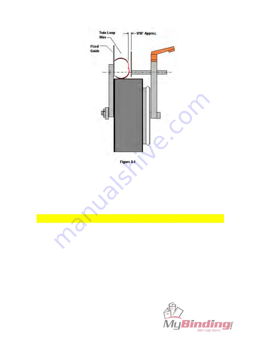
The upper and side guides should be adjusted so that the Twin Loop wire will travel back and forth
freely (see Figure 9-1) but without too much room to move around.
The following steps are
recommended:
1. Cut a 12” long piece of Twin Loop wire element from the supply chute and use it as a set-up
Sample.
2. Loosen the two adjustable handles for the upper guide and the side guides (see Figure 9-1).
3. Insert the 12” long sample as shown in Figure 9-1.
4. To set the .01 clearance, use three sheets of 20# bond paper as a gauge. Hold the open side of the
wire up against the sideplate of the feed assembly. Insert the three sheets of paper and slide the side
guide up against the paper. Tighten the handles to secure the guide and remove the paper.
5. Repeat step 4 for the upper guide.


